Infiniti G37 Coupe. Manual — part 594
ECM
EC-557
< ECU DIAGNOSIS >
[VQ37VHR]
C
D
E
F
G
H
I
J
K
L
M
A
EC
N
P
O
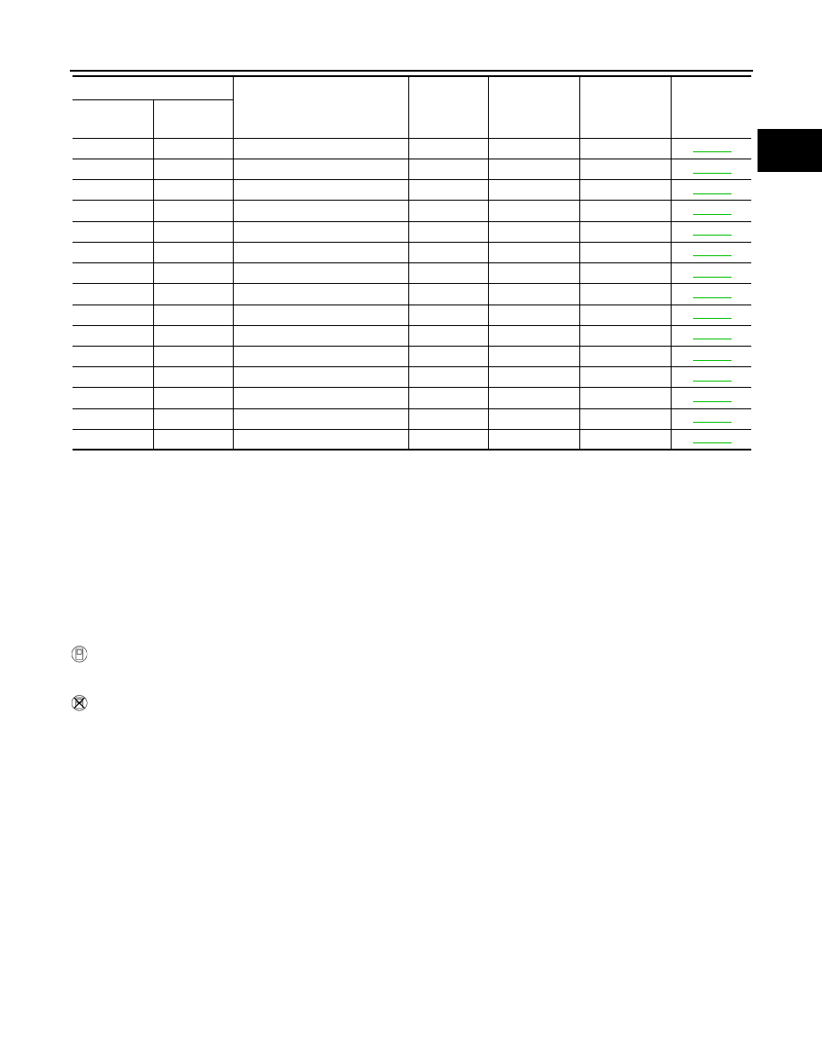
*1: 1st trip DTC No. is the same as DTC No.
*2: This number is prescribed by SAE J2012.
*3: In Diagnostic Test Mode II (Self-diagnostic results), this number is controlled by NISSAN.
*4: The troubleshooting for this DTC needs CONSULT-III.
*5: When the fail-safe operations for both self-diagnoses occur, the MIL illuminates.
*6: SRT code will not be set if the self-diagnostic result is NG.
*7: When the ECM is in the mode of displaying SRT status, MIL may flash. For the details, refer to “How to Display SRT Status”.
How to Set SRT Code
INFOID:0000000001734352
To set all SRT codes, self-diagnosis for the items indicated above must be performed one or more times. Each
diagnosis may require a long period of actual driving under various conditions.
WITH CONSULT-III
Perform corresponding DTC Confirmation Procedure one by one based on Performance Priority in the table
on “SRT Item”.
WITHOUT CONSULT-III
The most efficient driving pattern in which SRT codes can be properly set is explained on the next page. The
driving pattern should be performed one or more times to set all SRT codes.
P2100
2100
ETC MOT PWR-B1
—
1
×
P2101
2101
ETC FNCTN/CIRC-B1
—
1
×
P2103
2103
ETC MOT PWR
—
1
×
P2118
2118
ETC MOT-B1
—
1
×
P2119
2119
ETC ACTR-B1
—
1
×
P2122
2122
APP SEN 1/CIRC
—
1
×
P2123
2123
APP SEN 1/CIRC
—
1
×
P2127
2127
APP SEN 2/CIRC
—
1
×
P2128
2128
APP SEN 2/CIRC
—
1
×
P2132
2132
TP SEN 1/CIRC-B2
—
1
×
P2133
2133
TP SEN 1/CIRC-B2
—
1
×
P2135
2135
TP SENSOR-B1
—
1
×
P2138
2138
APP SENSOR
—
1
×
P2A00
2A00
A/F SENSOR1 (B1)
—
2
×
P2A03
2A03
A/F SENSOR1 (B2)
—
2
×
DTC*
1
Items
(CONSULT-III screen terms)
SRT code
Trip
MIL
Reference
page
CONSULT-III
GST*
2
ECM*
3
EC-558
< ECU DIAGNOSIS >
[VQ37VHR]
ECM
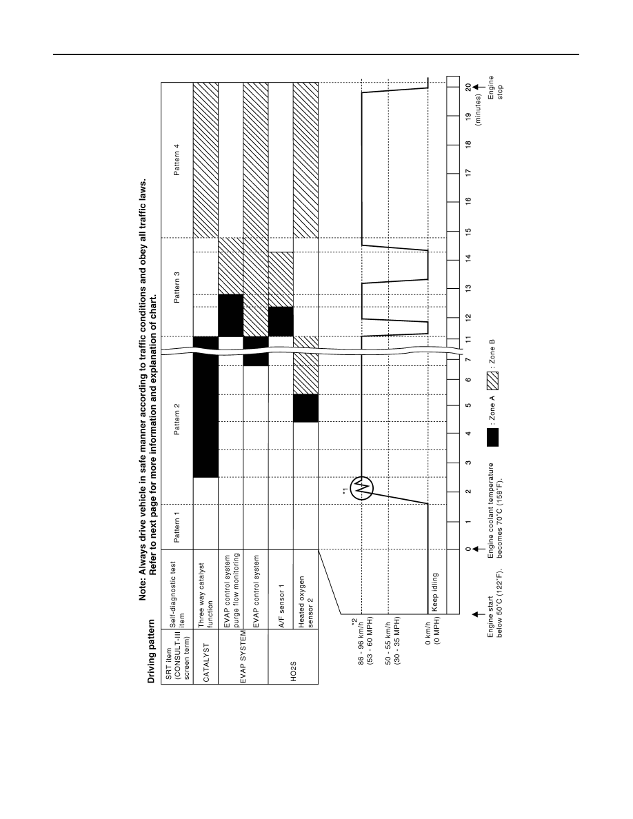
DRIVING PATTERN
• The time required for each diagnosis varies with road surface conditions, weather, altitude, individual driving
habits, etc.
Zone A refers to the range where the time, required for the diagnosis under normal conditions*, is the short-
est.
Zone B refers to the range where the diagnosis can still be performed if the diagnosis is not completed within
zone A.
*: Normal conditions refer to the following:
PBIB3455E
ECM
EC-559
< ECU DIAGNOSIS >
[VQ37VHR]
C
D
E
F
G
H
I
J
K
L
M
A
EC
N
P
O
• Sea level
• Flat road
• Ambient air temperature: 20 - 30
°
C (68 - 86
°
F)
• Diagnosis is performed as quickly as possible under normal conditions.
Under different conditions [For example: ambient air temperature other than 20 - 30
°
C (68 - 86
°
F)], diagno-
sis may also be performed.
Pattern 1:
• The engine is started at the engine coolant temperature of
−
10 to 35
°
C (14 to 95
°
F)
(where the voltage between the ECM terminal 71 and ground is 3.0 - 4.3V).
• The engine must be operated at idle speed until the engine coolant temperature is greater than 70
°
C
(158
°
F) (where the voltage between the ECM terminal 71 and ground is lower than 1.4V).
• The engine is started at the fuel tank temperature of warmer than 0
°
C (32
°
F) (where the voltage
between the ECM terminal 106 and ground is less than 4.1V).
Pattern 2:
• When steady-state driving is performed again even after it is interrupted, each diagnosis can be conducted.
In this case, the time required for diagnosis may be extended.
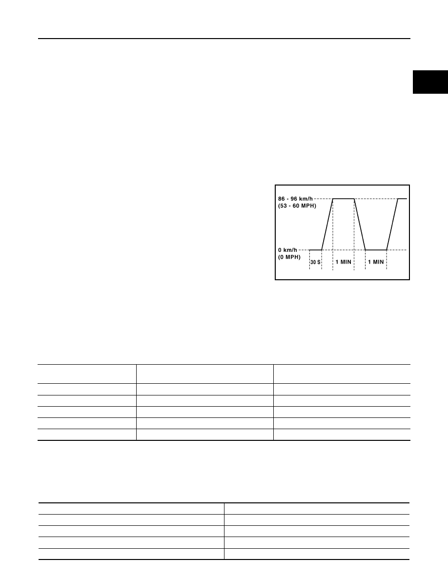
Pattern 3:
• Operate vehicle following the driving pattern shown in the figure.
• Release the accelerator pedal during decelerating vehicle speed
from 90 km/h (56 MPH) to 0 km/h (0 MPH).
Pattern 4:
• The accelerator pedal must be held very steady during steady-
state driving.
• If the accelerator pedal is moved, the test must be conducted all
over again.
*1: Depress the accelerator pedal until vehicle speed is 90 km/h (56
MPH), then release the accelerator pedal and keep it released for
more than 10 seconds. Depress the accelerator pedal until vehicle
speed is 90 km/h (56 MPH) again.
*2: Checking the vehicle speed with GST is advised.
Suggested Transmission Gear Position for A/T Models
Set the selector lever in the D position with the overdrive switch turned ON.
Suggested Upshift Speeds for M/T Models
Shown below are suggested vehicle speeds for shifting into a higher gear. These suggestions relate to fuel
economy and vehicle performance. Actual upshift speeds will vary according to road conditions, the weather
and individual driving habits.
Unit: km/h (MPH)
Suggested Maximum Speed in Each Gear
Downshift to a lower gear if the engine is not running smoothly, or if you need to accelerate.
Do not exceed the maximum suggested speed (shown below) in any gear. For level road driving, use the high-
est gear suggested for that speed. Always observe posted speed limits and drive according to the road condi-
tions to ensure sage operation. Do not over-rev the engine when shifting to a lower gear as it may cause
engine damage or loss of vehicle control.
PBIB2244E
Gear change
For normal acceleration in low altitude areas
[less than 1,219 m (4,000 ft)]
For quick acceleration in low altitude areas or in
high altitude areas [over 1,219 m (4,000 ft)]
1st to 2nd
13 (8)
24 (15)
2nd to 3rd
26 (16)
40 (25)
3rd to 4th
40 (25)
64 (40)
4th to 5th
50 (30)
72 (45)
5th to 6th
53 (33)
80 (50)
Gear
km/h (MPH)
1st
63 (39)
2nd
103 (64)
3rd
148 (92)
4th
—

EC-560
< ECU DIAGNOSIS >
[VQ37VHR]
ECM
Test Value and Test Limit
INFOID:0000000001734353
The following is the information specified in Service $06 of SAE J1979.
The test value is a parameter used to determine whether a system/circuit diagnostic test is OK or NG while
being monitored by the ECM during self-diagnosis. The test limit is a reference value which is specified as the
maximum or minimum value and is compared with the test value being monitored.
These data (test value and test limit) are specified by Test ID (TID) and Component ID (CID) and can be dis-
played on the GST screen.
5th
—
6th
—
Gear
km/h (MPH)
Item
OBD-
MID
Self-diagnostic test item
DTC
Test value and Test
limit
(GST display)
Description
TID
Unit and
Scaling
ID
HO2S
01H
Air fuel ratio (A/F) sensor 1
(Bank 1)
P0131
83H
0BH
Minimum sensor output voltage
for test cycle
P0131
84H
0BH
Maximum sensor output voltage
for test cycle
P0130
85H
0BH
Minimum sensor output voltage
for test cycle
P0130
86H
0BH
Maximum sensor output voltage
for test cycle
P0133
87H
04H
Response rate: Response ratio
(Lean to Rich)
P0133
88H
04H
Response rate: Response ratio
(Rich to Lean)
P2A00
89H
84H
The amount of shift in air fuel ratio
P2A00
8AH
84H
The amount of shift in air fuel ratio
P0130
8BH
0BH
Difference in sensor output volt-
age
P0133
8CH
83H
Response gain at the limited fre-
quency
02H
Heated oxygen sensor 2
(Bank 1)
P0138
07H
0CH
Minimum sensor output voltage
for test cycle
P0137
08H
0CH
Maximum sensor output voltage
for test cycle
P0138
80H
0CH
Sensor output voltage
P0139
81H
0CH
Difference in sensor output volt-
age
03H
Heated oxygen sensor 3
(Bank 1)
P0143
07H
0CH
Minimum sensor output voltage
for test cycle
P0144
08H
0CH
Maximum sensor output voltage
for test cycle
P0146
80H
0CH
Sensor output voltage
P0145
81H
0CH
Difference in sensor output volt-
age
Нет комментариевНе стесняйтесь поделиться с нами вашим ценным мнением.
Текст