Infiniti G37 Coupe. Manual — part 1328

SHIFT POSITION INDICATOR CIRCUIT
TM-165
< COMPONENT DIAGNOSIS >
[5AT: RE5R05A]
C
E
F
G
H
I
J
K
L
M
A
B
TM
N
O
P
SHIFT POSITION INDICATOR CIRCUIT
Description
INFOID:0000000001672208
TCM transmit the switch signals to unified meter and A/C amp. by CAN communication line. Then manual
mode switch position is indicated on the shift position indicator.
Component Function Check
INFOID:0000000001672209
1.
CHECK A/T INDICATOR
1.
Start the engine.
2.
Drive vehicle in the manual mode, and confirm that the actual gear position and the meter's indication of
the position mutually coincide when the selector lever is shifted to the “UP (+ side)” or “DOWN (
−
side)”
side (1st
⇔
5th gear).
Is the inspection result normal?
YES
>> INSPECTION END
NO
>> Go to
Diagnosis Procedure
INFOID:0000000001672210
1.
CHECK INPUT SIGNALS
With CONSULT-III
1.
Start the engine.
2.
Select “GEAR” on “DATA MONITOR” and read out the value.
3.
Drive vehicle in the manual mode, and confirm that the actual gear position and the meter's indication of
the position mutually coincide when the selector lever is shifted to the “UP (+ side)” or “DOWN (
−
side)”
side (1st
⇔
5th gear).
Is the inspection result normal?
YES
>> INSPECTION END
NO-1
>>
The actual gear position does not change, or shifting into the manual mode is not possible (no
gear shifting in the manual mode possible). Or the shift position indicator is not indicated.
• Check manual mode switch. Refer to
TM-161, "Component Inspection (Manual Mode Switch)"
• Check A/T main system (Fail-safe function actuated).
- Perform “SELF-DIAG RESULTS” mode for “TRANSMISSION”. Refer to
.
NO-2
>>
The actual gear position changes, but the shift position indicator is not indicated.
• Perform “SELF-DIAG RESULTS” mode for “TRANSMISSION”. Refer to
.
NO-3
>>
The actual gear position and the indication on the shift position indicator do not coincide.
• Perform “SELF-DIAG RESULTS” mode for “TRANSMISSION”. Refer to
.
NO-4
>>
Only a specific position or positions is/are not indicated on the shift position indicator.
• Check the unified meter and A/C amp. Refer to
.

TM-166
< COMPONENT DIAGNOSIS >
[5AT: RE5R05A]
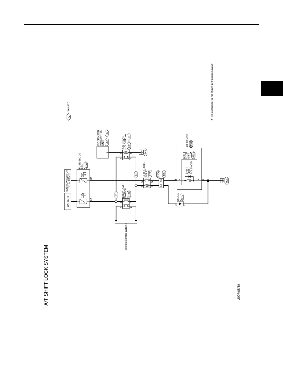
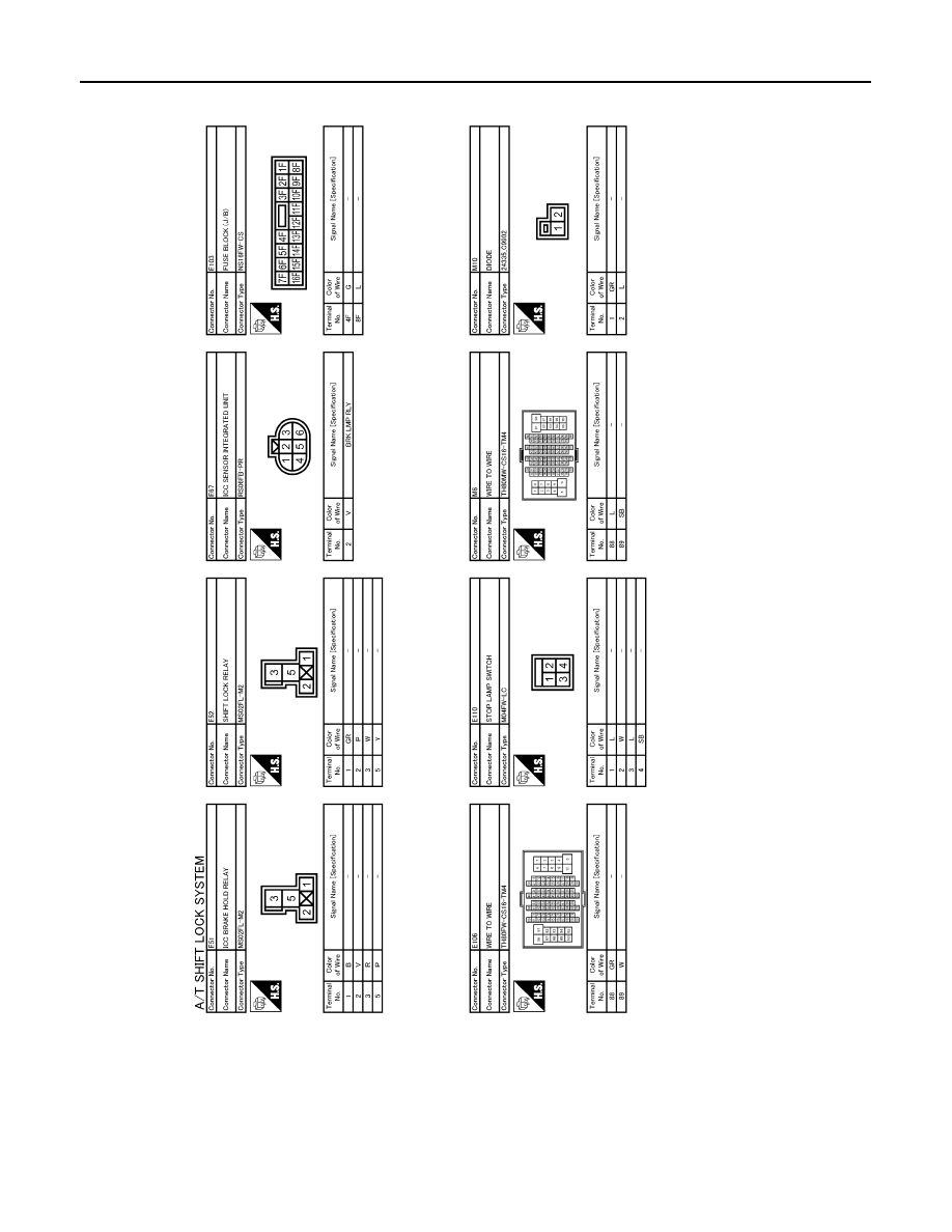
SHIFT LOCK SYSTEM
SHIFT LOCK SYSTEM
Description
INFOID:0000000001672211
Shift lock system circuit consists of the following part.
Wiring Diagram - A/T SHIFT LOCK SYSTEM -
INFOID:0000000001672212
Click here to view the eWD.
Component
Function
Shift lock solenoid
Activated by the ignition switch and stop lamp signals, it holds the relative positions of sliders A and
B.
Shift lock relay
Current flow to stop lamp switch allows shift lock solenoid contact ON, and then power is applied to
shift lock solenoid.
Stop lamp switch
Depressing the brake pedal turns ON the stop lamp switch and energizes the shift lock relay.
SHIFT LOCK SYSTEM
TM-167
< COMPONENT DIAGNOSIS >
[5AT: RE5R05A]
C
E
F
G
H
I
J
K
L
M
A
B
TM
N
O
P
JCDWA0126GB
TM-168
< COMPONENT DIAGNOSIS >
[5AT: RE5R05A]
SHIFT LOCK SYSTEM
JCDWA0127GB
Нет комментариевНе стесняйтесь поделиться с нами вашим ценным мнением.
Текст