Infiniti G37 Coupe. Manual — part 1362
TRANSMISSION ASSEMBLY
TM-301
< DISASSEMBLY AND ASSEMBLY >
[5AT: RE5R05A]
C
E
F
G
H
I
J
K
L
M
A
B
TM
N
O
P
ii.
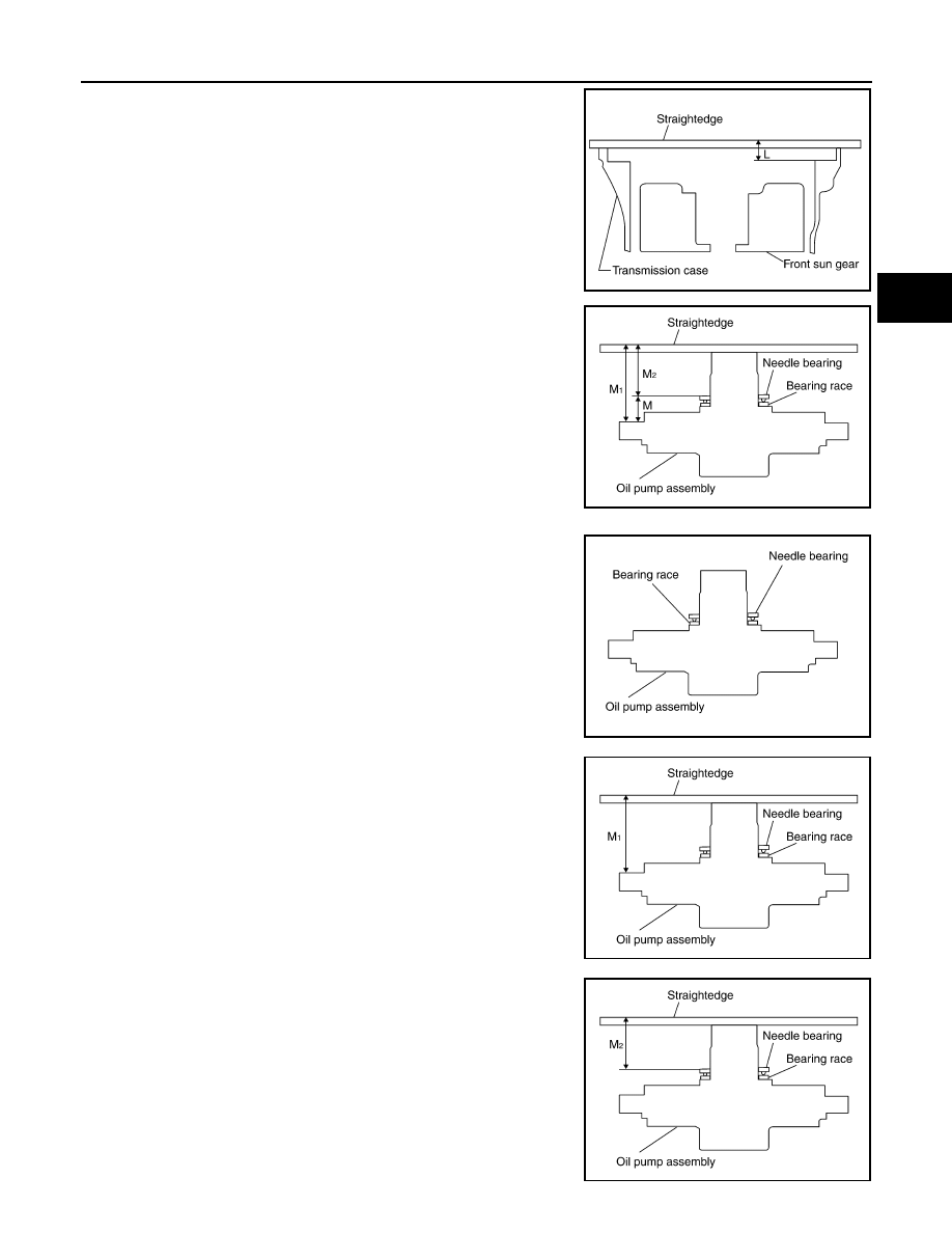
Measure dimension “L”.
iii.
Calculate dimension “J”.
b.
Measure dimensions “M
1
” and “M
2
” and then calculate dimen-
sion “M”.
i.
Place bearing race and needle bearing on oil pump assembly.
ii.
Measure dimension “M
1
”.
iii.
Measure dimension “M
2
”.
“J”
: Distance between oil pump fitting surface of
transmission case and needle bearing mating
surface of front sun gear.
J = K – L
SCIA5352E
SCIA3125E
SCIA3124E
SCIA3126E
SCIA3127E
TM-302
< DISASSEMBLY AND ASSEMBLY >
[5AT: RE5R05A]
TRANSMISSION ASSEMBLY
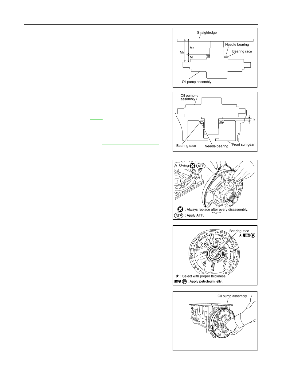
iv.
Calculate dimension “M”.
c.
Adjust total end play “T
1
”.
• Select proper thickness of bearing race so that total end play
is within specifications.
57. Install O-ring to oil pump assembly.
58. Install bearing race to oil pump assembly.
59. Install oil pump assembly in transmission case.
CAUTION:
Apply ATF to oil pump bearing.
“M”
: Distance between transmission case fitting
surface of oil pump and needle bearing on oil
pump.
M = M
1
– M
2
SCIA3125E
T
1
= J – M
Total end play “T
1
”
: Refer to
.
Bearing races
: Refer to
.
SCIA2810E
SCIA5172E
SCIA6529E
SCIA2811E
TRANSMISSION ASSEMBLY
TM-303
< DISASSEMBLY AND ASSEMBLY >
[5AT: RE5R05A]
C
E
F
G
H
I
J
K
L
M
A
B
TM
N
O
P
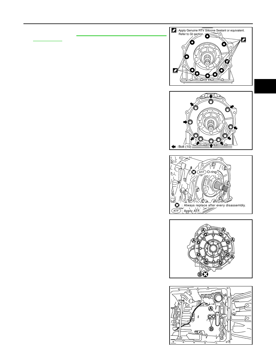
60. Apply recommended sealant (Genuine RTV Silicone Sealant or
GI-15, "Recommended Chemical Products
.) to oil pump assembly as shown in the figure.
CAUTION:
Completely remove all moisture, oil and old sealant, etc.
from the oil pump mounting bolts and oil pump mounting
bolt mounting surfaces.
61. Tighten oil pump bolts to the specified torque.
CAUTION:
Apply ATF to oil pump bushing.
62. Install O-ring to input clutch assembly.
63. Install converter housing to transmission case, and then tighten
converter housing bolts (A) and self-sealing bolt (B) to the spec-
ified torque.
64. Make sure that brake band (A) does not close turbine revolution
sensor hole (B).
SCIA5321E
SCIA2300E
SCIA5011E
SCIA8085E
JPDIA0020ZZ

TM-304
< DISASSEMBLY AND ASSEMBLY >
[5AT: RE5R05A]
TRANSMISSION ASSEMBLY
65. Connect TCM connector (A) and park/neutral position switch
connector (B).
66. Install A/T assembly harness connector (A) to control valve with
TCM.
67. Connect TCM connectors (A) and (B).
68. Install O-ring (1) to A/T assembly harness connector (A).
69. Install bracket (1) to A/T fluid temperature sensor 2 (2).
JPDIA0018ZZ
JPDIA0019ZZ
JPDIA0016ZZ
JPDIA0015ZZ
JPDIA0014ZZ
Нет комментариевНе стесняйтесь поделиться с нами вашим ценным мнением.
Текст