Infiniti G37 Coupe. Manual — part 1409
WT-8
< FUNCTION DIAGNOSIS >
TPMS
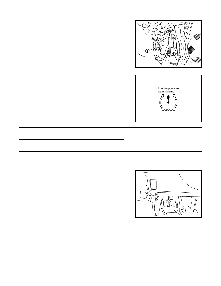
The BCM (1) reads the air pressure signal received by the tire pres-
sure receiver, and controls the low tire pressure warning lamp and
the buzzer operations. It also has a judgment function to detect a
system malfunction.
LOW TIRE PRESSURE WARNING LAMP
The unified meter and A/C amp receives tire pressure status from
the BCM using CAN communication. When BCM judges from a
transmitter signal that tire pressure is insufficient, BCM transmits a
signal to unified meter and A/C amp through CAN communication.
unified meter and A/C amp turns on the low tire pressure warning
lamp mounted on the Combination meter.
Low tire pressure warning lamp indication
NOTE1: Standard air pressure is for 230 kPa (2.3 kg/cm
2
, 33 psi) vehicles.
NOTE2: Standard air pressure is for 240 kPa (2.4 kg/cm
2
, 35 psi) vehicles.
TIRE PRESSURE WARNING CHECK SWITCH
The following item can be checked by grounding the tire pressure
warning check switch (1) harness connector terminal.
• The low tire pressure warning lamp in the combination meter will
blinks according to the self-diagnostic results.
JPEIC0002ZZ
SEIA0434E
Condition
Low tire pressure warning lamp
Less than 182.7 kPa (1.9 kg/cm
2
, 26 psi) [NOTE1]
ON
Less than 189.6 kPa (1.9 kg/cm
2
, 27 psi) [NOTE2]
Low tire pressure warning system malfunction [Other diagnostic item]
Warning lamp blinks 1 min, then turns ON.
JPEIC0003ZZ

TPMS
WT-9
< FUNCTION DIAGNOSIS >
C
D
F
G
H
I
J
K
L
M
A
B
WT
N
O
P
Component Parts Location
INFOID:0000000001686950
Component Description
INFOID:0000000001686951
1.
Transmitter
2.
BCM
3.
Tire pressure receiver
4.
Tire pressure warning check switch
5.
Low tire pressure warning lamp
6.
Unified meter and A/C amp
A.
Wheel
B.
Dash side lower (passenger side)
C.
Upper instrument assist lower panel
D.
Behind instrument lower panel
(driver side)
E.
Inside combination meter
F.
Behind cluster lid C
JPEIC0028ZZ
Component parts
Function
BCM (Body Control Module)
.
Transmitter
.
Tire pressure receiver
.
Tire pressure warning check switch
.
Turn signal lamp
ID registration of each wheel has been completed, turn signal lamp flashes.
Combination meter
Controls a low tire pressure warning lamp, turn signal lamp, and buzzer by signals from the
unified meter and A/C amp.
Low tire pressure warning lamp
Illuminates if malfunction is detected in electrical system of TPMS.
Unified meter and A/C amp.
Transmits the vehicle speed signal via CAN communication to BCM.
Receives the tire pressure signal via CAN communication to BCM.

WT-10
< FUNCTION DIAGNOSIS >
DIAGNOSIS SYSTEM (BCM)
DIAGNOSIS SYSTEM (BCM)
COMMON ITEM
COMMON ITEM : CONSULT-III Function (BCM - COMMON ITEM)
INFOID:0000000001903111
APPLICATION ITEM
CONSULT-III performs the following functions via CAN communication with BCM.
SYSTEM APPLICATION
BCM can perform the following functions for each system.
NOTE:
It can perform the diagnosis modes except the following for all sub system selection items.
*: This item is displayed, but is not used.
FREEZE FRAME DATA (FFD) AND IGN COUNTER
Freeze Frame Data
The BCM records the following condition at the moment a particular DTC is detected.
• Vehicle Speed
• Odd Trip Meter
Diagnosis mode
Function Description
Work Support
Changes the setting for each system function.
Self Diagnostic Result
Displays the diagnosis results judged by BCM.
CAN DIAG SUPPORT MNTR
Monitors the reception status of CAN communication viewed from BCM. Refer to CONSULT-III opera-
tion manual.
Data Monitor
The BCM input/output signals are displayed.
Active Test
The signals used to activate each device are forcibly supplied from BCM.
Ecu Identification
The BCM part number is displayed.
Configuration
This function is not used even though it is displayed.
System
Sub system selection item
Diagnosis mode
Work Support
Data Monitor
Active Test
Door lock
DOOR LOCK
×
×
×
Rear window defogger
REAR DEFOGGER
×
×
Warning chime
BUZZER
×
×
Interior room lamp timer
INT LAMP
×
×
×
Exterior lamp
HEAD LAMP
×
×
×
Wiper and washer
WIPER
×
×
×
Turn signal and hazard warning lamps
FLASHER
×
×
×
Air conditioner*
AIR CONDITONER
×
Intelligent Key system
INTELLIGENT KEY
×
×
×
Combination switch
COMB SW
×
BCM
BCM
×
IVIS - NATS
IMMU
×
×
Interior room lamp battery saver
BATTERY SAVER
×
×
×
Trunk open
TRUNK
×
Vehicle security system
THEFT ALM
×
×
×
RAP system
RETAINED PWR
×
Signal buffer system
SIGNAL BUFFER
×
×
TPMS
TPMS (AIR PRESSURE MONITOR)
×
×
×

DIAGNOSIS SYSTEM (BCM)
WT-11
< FUNCTION DIAGNOSIS >
C
D
F
G
H
I
J
K
L
M
A
B
WT
N
O
P
• Vehicle Condition (BCM detected condition)
IGN Counter
IGN counter indicates the number of times that ignition switch is turned ON after DTC is detected.
• The number is 0 when a malfunction is detected now.
• The number increases like 1
→
2
→
3...38
→
39 after returning to the normal condition whenever ignition
switch OFF
→
ON.
• The number is fixed to 39 until the self-diagnosis results are erased if it is over 39.
AIR PRESSURE MONITOR
AIR PRESSURE MONITOR : Diagnosis Description
INFOID:0000000001686953
DESCRIPTION
During driving, the TPMS receives the signal transmitted from the transmitter installed in each wheel, when
the tire pressure becomes low. The control unit (BCM) of this system has pressure judgment and trouble diag-
nosis functions.
When the TPMS detects low inflation pressure or another unusual symptom, the low tire pressure warning
lamps in the combination meter comes on.
SELF DIAGNOSTIC PROCEDURE (WITH CONSULT-III)
With CONSULT-III
Touch “SELF-DIAG RESULT” display shows malfunction experienced since the last erasing operation. Refer
to
.
SELF DIAGNOSTIC PROCEDURE (WITHOUT CONSULT-III)
Without CONSULT-III
To start the self-diagnostic results mode, ground terminal of the tire pressure warning check connector. The
malfunction location is indicated by the low tire pressure warning lamp blinking.
CONSULT screen terms
Description
SLEEP>LOCK
While turning BCM status from low power consumption mode to normal mode (Power supply
position is “LOCK”)
SLEEP>OFF
While turning BCM status from low power consumption mode to normal mode (Power supply
position is “OFF”.)
LOCK>ACC
While turning power supply position from “LOCK” to “ACC”
ACC>ON
While turning power supply position from “ACC” to “IGN”
RUN>ACC
While turning power supply position from “RUN” to “ACC” (Vehicle is stopping and selector
lever is except P position.)
CRANK>RUN
While turning power supply position from “CRANKING” to “RUN” (From cranking up the en-
gine to run it)
RUN>URGENT
While turning power supply position from “RUN“ to “ACC” (Emergency stop operation)
ACC>OFF
While turning power supply position from “ACC” to “OFF”
OFF>LOCK
While turning power supply position from “OFF” to “LOCK”
OFF>ACC
While turning power supply position from “OFF” to “ACC”
ON>CRANK
While turning power supply position from “IGN” to “CRANKING”
OFF>SLEEP
While turning BCM status from normal mode (Power supply position is “OFF”.) to low power
consumption mode
LOCK>SLEEP
While turning BCM status from normal mode (Power supply position is “LOCK”.) to low pow-
er consumption mode
LOCK
Power supply position is “LOCK” (Ignition switch OFF with steering is locked.)
OFF
Power supply position is “OFF” (Ignition switch OFF with steering is unlocked.)
ACC
Power supply position is “ACC” (Ignition switch ACC)
ON
Power supply position is “IGN” (Ignition switch ON with engine stopped)
ENGINE RUN
Power supply position is “RUN” (Ignition switch ON with engine running)
CRANKING
Power supply position is “CRANKING” (At engine cranking)
Нет комментариевНе стесняйтесь поделиться с нами вашим ценным мнением.
Текст