Infiniti G37 Coupe. Manual — part 270
BRC-54
< COMPONENT DIAGNOSIS >
[VDC/TCS/ABS]
C1121, C1123, C1125, C1127 OUT ABS SOL
NO
>> Go to diagnosis procedure. Refer to
Special Repair Requirement
INFOID:0000000001664571
1.
ADJUSTMENT OF STEERING ANGLE SENSOR NEUTRAL POSITION
Always perform the neutral position adjustment for the steering angle sensor, when replacing the ABS actua-
tor and electric unit (control unit). Refer to
BRC-8, "ADJUSTMENT OF STEERING ANGLE SENSOR NEU-
>> END
C1130, C1131, C1132 ENGINE SIGNAL
BRC-55
< COMPONENT DIAGNOSIS >
[VDC/TCS/ABS]
C
D
E
G
H
I
J
K
L
M
A
B
BRC
N
O
P
C1130, C1131, C1132 ENGINE SIGNAL
Description
INFOID:0000000001635087
ABS actuator and electric unit (control unit) and ECM exchange the engine signal with CAN communication
line.
DTC Logic
INFOID:0000000001635088
DTC DETECTION LOGIC
DTC CONFIRMATION PROCEDURE
1.
CHECK SELF-DIAGNOSIS RESULTS
Check the self-diagnosis results.
Is above displayed on the self-diagnosis display?
YES
>> Proceed to diagnosis procedure. Refer to
.
NO
>> INSPECTION END
Diagnosis Procedure
INFOID:0000000001635089
1.
CHECK ENGINE SYSTEM
1.
Perform ECM self-diagnosis. Repair or replace items indicated, then perform ECM self-diagnosis again.
2.
Perform ABS actuator and electric unit (control unit) self-diagnosis.
Is any item indicated on the self-diagnosis display?
YES
>> Repair or replace the affected part.
NO
>> INSPECTION END
Special Repair Requirement
INFOID:0000000001635090
1.
ADJUSTMENT OF STEERING ANGLE SENSOR NEUTRAL POSITION
Always perform the neutral position adjustment for the steering angle sensor, when replacing the ABS actua-
tor and electric unit (control unit). Refer to
BRC-8, "ADJUSTMENT OF STEERING ANGLE SENSOR NEU-
>> END
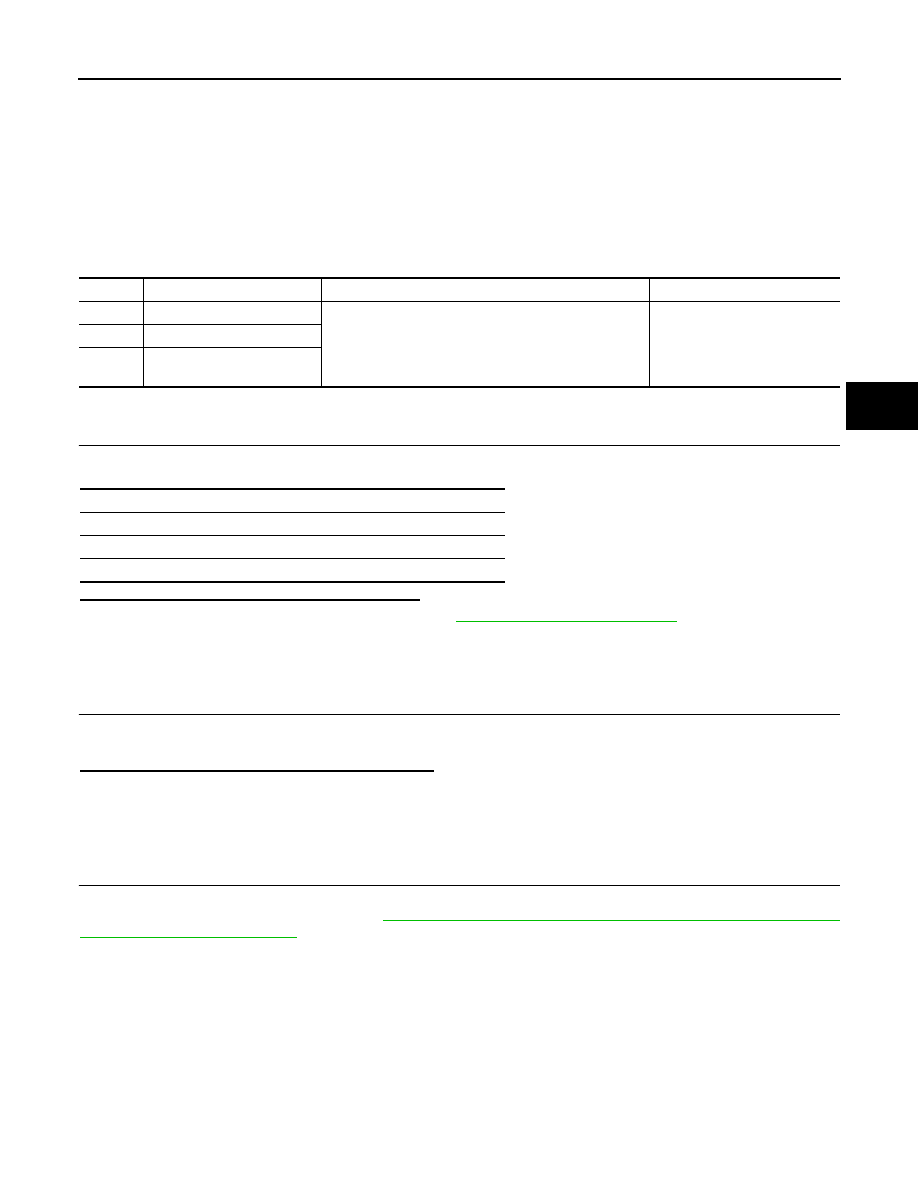
DTC
Display item
Malfunction detected condition
Possible cause
C1130
ENGINE SIGNAL 1
Major engine components are malfunctioning.
• Harness or connector
• ABS actuator and electric unit
(control unit)
• ECM
• CAN communication line
C1131
ENGINE SIGNAL 2
C1132
ENGINE SIGNAL 3
Self-diagnosis results
ENGINE SIGNAL 1
ENGINE SIGNAL 2
ENGINE SIGNAL 3

BRC-56
< COMPONENT DIAGNOSIS >
[VDC/TCS/ABS]
C1138 4WAS SYSTEM
C1138 4WAS SYSTEM
Description
INFOID:0000000001635091
The ABS actuator and electric unit (control unit) and the 4WAS control unit exchange signals via the CAN
communication line.
DTC Logic
INFOID:0000000001635092
DTC DETECTION LOGIC
DTC CONFIRMATION PROCEDURE
1.
CHECK SELF-DIAGNOSIS RESULTS
Check the self-diagnosis results.
Is above displayed on the self-diagnosis display?
YES
>> Proceed to diagnosis procedure. Refer to
.
NO
>> INSPECTION END
Diagnosis Procedure
INFOID:0000000001635093
1.
CHECK 4WAS SYSTEM
1.
Perform 4WAS front control unit self-diagnosis and 4WAS main control unit self-diagnosis. Repair or
replace items indicated, then perform 4WAS front control unit self-diagnosis and 4WAS main control unit
self-diagnosis again.
2.
Perform ABS actuator and electric unit (control unit) self-diagnosis.
Is any item indicated on the self-diagnosis display?
YES
>> Repair or replace the affected part.
NO
>> INSPECTION END
Special Repair Requirement
INFOID:0000000001635094
1.
ADJUSTMENT OF STEERING ANGLE SENSOR NEUTRAL POSITION
Always perform the neutral position adjustment for the steering angle sensor, when replacing the ABS actua-
tor and electric unit (control unit). Refer to
BRC-8, "ADJUSTMENT OF STEERING ANGLE SENSOR NEU-
>> END
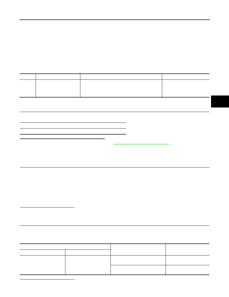
DTC
Display item
Malfunction detected condition
Possible cause
C1138
4WAS CIRCUIT
Abnormal condition in major 4WAS parts.
• ABS actuator and electric unit
(control unit)
• 4WAS system
• CAN communication line
Self-diagnosis results
4WAS CIRCUIT
C1142 PRESS SENSOR
BRC-57
< COMPONENT DIAGNOSIS >
[VDC/TCS/ABS]
C
D
E
G
H
I
J
K
L
M
A
B
BRC
N
O
P
C1142 PRESS SENSOR
Description
INFOID:0000000001635095
The pressure sensor converts the brake fluid pressure to an electric signal and transmits it to the ABS actuator
and electric unit (control unit). [The pressure sensor is integrated in the ABS actuator and electric unit (control
unit).]
DTC Logic
INFOID:0000000001635096
DTC DETECTION LOGIC
DTC CONFIRMATION PROCEDURE
1.
CHECK SELF-DIAGNOSIS RESULTS
Check the self-diagnosis results.
Is above displayed on the self-diagnosis display?
YES
>> Proceed to diagnosis procedure. Refer to
.
NO
>> INSPECTION END
Diagnosis Procedure
INFOID:0000000001635097
1.
CHECK STOP LAMP SWITCH CONNECTOR
1.
Turn ignition switch OFF.
2.
Disconnect ABS actuator and electric unit (control unit) connector.
3.
Disconnect stop lamp switch connector.
4.
Check terminal for deformation, disconnection, looseness, and so on. If any malfunction is found, repair or
replace terminal.
5.
Reconnect connectors securely.
6.
Start engine.
7.
Repeat pumping brake pedal carefully several times, and perform self-diagnosis.
Is the inspection result normal?
YES
>> GO TO 2.
NO
>> Poor connection of connector terminal. Repair or replace connector.
2.
CHECK STOP LAMP SWITCH
1.
Turn ignition switch OFF.
2.
Disconnect stop lamp switch connector.
3.
Check continuity between stop lamp switch connector terminals.
Is the inspection result normal?
YES
>> GO TO 3.
DTC
Display item
Malfunction detected condition
Possible cause
C1142
PRESS SEN CIRCUIT
Pressure sensor signal line is open or shorted, or pres-
sure sensor is malfunctioning.
• Harness or connector
• Stop lamp switch
• ABS actuator and electric unit
(control unit)
Self-diagnosis results
PRESS SEN CIRCUIT
Stop lamp switch
Condition
Continuity
Connector
Terminal
E110
1 – 2 (Without ICC models)
3
−
4 (With ICC models)
Release stop lamp switch
(When brake pedal is depressed.)
Existed
Push stop lamp switch
(When brake pedal is released.)
Not existed
Нет комментариевНе стесняйтесь поделиться с нами вашим ценным мнением.
Текст