Infiniti G37 Coupe. Manual — part 1066
RSU-14
< ON-VEHICLE REPAIR >
SUSPENSION ARM
SUSPENSION ARM
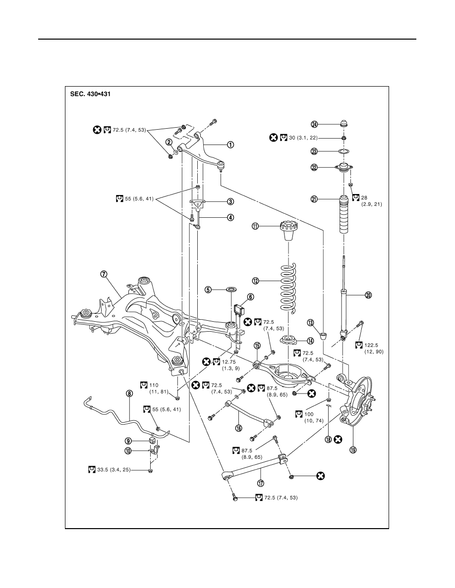
Exploded View
INFOID:0000000001686608
1.
Suspension arm
2.
Stopper rubber
3.
Stabilizer connecting rod mounting
bracket
4.
Stabilizer connecting rod
5.
Mount stopper
6.
Damper assembly
JPEIB0059ZZ
SUSPENSION ARM
RSU-15
< ON-VEHICLE REPAIR >
C
D
F
G
H
I
J
K
L
M
A
B
RSU
N
O
P
Removal and Installation
INFOID:0000000001671758
REMOVAL
1.
Remove tire with power tool.
2.
Remove torque member mounting bolts with power tool. Hang torque member in a place where it will not
interfere with work. Refer to
BR-56, "BRAKE CALIPER ASSEMBLY (1 PISTON TYPE) : Exploded View"
(1 piston type),
BR-59, "BRAKE CALIPER ASSEMBLY (2 PISTON TYPE) : Exploded View"
type).
3.
Set suitable jack under axle assembly to relieve the coil spring tension.
4.
Remove connecting rod mounting bracket from suspension arm with power tool.
5.
Remove drive shaft. Refer to
.
6.
Remove height sensor (with xenon headlamp). Refer to
7.
Remove cotter pin of suspension arm ball joint, and loosen nut.
8.
Remove mounting bolts and nuts between suspension arm and rear suspension member.
9.
Use the ball joint remover to remove suspension arm from axle assembly. Be careful not to damage ball
joint boot.
CAUTION:
Tighten temporarily mounting nut to prevent damage to threads and to prevent ball joint remover
from coming off.
10. Remove suspension arm.
INSTALLATION
Note the following and, install in the reverse order of removal.
• Perform final tightening of rear suspension member installation position (rubber bussing), under unladen
conditions with tires on level ground.
Inspection
INFOID:0000000001671759
INSPECTION AFTER REMOVAL
Visual Inspection
• Check suspension arm and bushing for deformation, cracks or damage. If any non-standard condition is
found, replace it.
• Check boot of ball joint for cracks or damage, and also for grease leakage. If a malfunction is detected,
replace suspension arm.
Ball Joint Inspection
Manually move ball stud at least ten times by hand to check for smooth movement.
Swing Torque Inspection
7.
Suspension member
8.
Stabilizer bar
9.
Stabilizer bushing
10. Stabilizer clamp
11. Upper seat
12. Coil spring
13. Ball seat
14. Rubber seat
15. Rear lower link
16. Front lower link
17. Radius rod
18. Cotter pin
19. Axle assembly
20. Shock absorber
21. Bound bumper cover
22. Shock absorber mounting bracket
23. Mounting seal
24. Cap
for symbols in the figure.
RSU-16
< ON-VEHICLE REPAIR >
SUSPENSION ARM
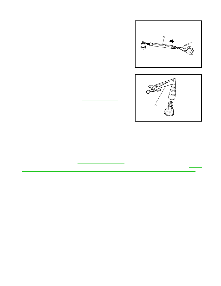
• Hook spring balance (A) at cotter pin mounting hole. Confirm
spring balance measurement value is within specifications when
ball stud begins moving.
- If it is outside the specified range, replace suspension arm assem-
bly.
Rotating Torque Inspection
• Attach the mounting nut to ball stud. Make sure that rotating torque
is within the specifications with a preload gauge (A)
[SST:ST3127S000 (J-25765-A)].
- If it is outside the specified range, replace suspension arm assem-
bly.
Axial End Play Inspection
• Move tip of ball stud in axial direction to check for looseness.
- If it is outside the specified range, replace suspension arm assembly.
INSPECTION AFTRE INSTALLATION
• Check wheel alignment. Refer to
• Adjust neutral position of steering angle sensor after checking the wheel alignment. Refer to
"ADJUSTMENT OF STEERING ANGLE SENSOR NEUTRAL POSITION : Special Repair Requirement"
.
Standard
Swing torque
: Refer to
.
JPEIA0005ZZ
Standard
Rotating torque
: Refer to
.
PDIA1258E
Standard
Axial end play
: Refer to
.
RADIUS ROD
RSU-17
< ON-VEHICLE REPAIR >
C
D
F
G
H
I
J
K
L
M
A
B
RSU
N
O
P
RADIUS ROD
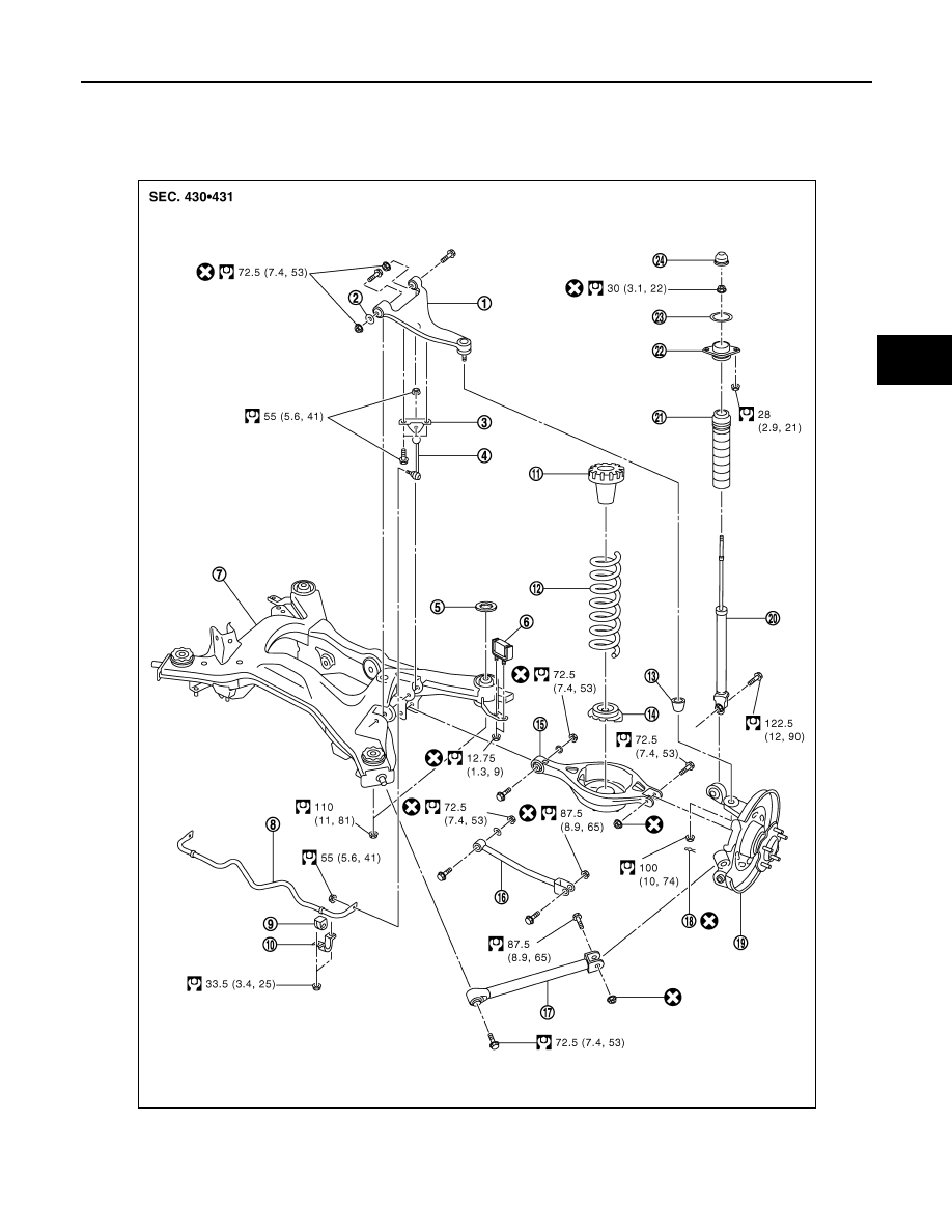
Exploded View
INFOID:0000000001686609
1.
Suspension arm
2.
Stopper rubber
3.
Stabilizer connecting rod mounting
bracket
4.
Stabilizer connecting rod
5.
Mount stopper
6.
Damper assembly
JPEIB0059ZZ
Нет комментариевНе стесняйтесь поделиться с нами вашим ценным мнением.
Текст