Infiniti G37 Coupe. Manual — part 374

U1000 CAN COMM CIRCUIT
DLK-57
< COMPONENT DIAGNOSIS >
[INTELLIGENT KEY SYSTEM]
C
D
E
F
G
H
I
J
L
M
A
B
DLK
N
O
P
COMPONENT DIAGNOSIS
U1000 CAN COMM CIRCUIT
Description
INFOID:0000000001683043
CAN (Controller Area Network) is a serial communication line for real time applications. It is an on-vehicle mul-
tiplex communication line with high data communication speed and excellent error detection ability. Modern
vehicles are equipped with many electronic control unit, and each control unit shares information and links
with other control units during operation (not independent). In CAN communication, control units are con-
nected with 2 communication lines (CAN H-line, CAN L-line) allowing a high rate of information transmission
with less wiring. Each control unit transmits/receives data but selectively reads required data only.
CAN Communication Signal Chart. Refer to
LAN-25, "CAN Communication Signal Chart"
DTC Logic
INFOID:0000000001683044
DTC DETECTION LOGIC
Diagnosis Procedure
INFOID:0000000001683045
1.
PERFORM SELF-DIAGNOSTIC
1.
Turn ignition switch ON and wait for 2 seconds or more.
2.
Check “Self Diagnostic Result”.
Is “CAN COMM CIRCUIT” displayed?
YES
>> Refer to
LAN-16, "Trouble Diagnosis Flow Chart"
NO
>> Refer to
GI-38, "Intermittent Incident"
.
DTC
CONSULT-III display
description
DTC Detection Condition
Possible cause
U1000
CAN COMM CIRCUIT
When BCM cannot communicate CAN com-
munication signal continuously for 2 sec-
onds or more.
In CAN communication system, any item (or items)
of the following listed below is malfunctioning.
• Transmission
• Receiving (ECM)
• Receiving (VDC/TCS/ABS)
• Receiving (METER/M&A)
• Receiving (TCM)
• Receiving (MULTI AV)
• Receiving (IPDM E/R)

DLK-58
< COMPONENT DIAGNOSIS >
[INTELLIGENT KEY SYSTEM]
U1010 CONTROL UNIT (CAN)
U1010 CONTROL UNIT (CAN)
DTC Logic
INFOID:0000000001683046
DTC DETECTION LOGIC
Diagnosis Procedure
INFOID:0000000001683047
1.
REPLACE BCM
When DTC [U1010] is detected, replace BCM.
>> Replace BCM.
Special Repair Requirement
INFOID:0000000001683048
1.
REQUIRED WORK WHEN REPLACING BCM
Initialize control unit. Refer to CONSULT-III operation manual NATS-IVIS/NVIS.
>> Work end.
DTC
CONSULT-III display de-
scription
DTC Detection Condition
Possible cause
U1010
CONTROL UNIT (CAN)
BCM detected internal CAN communication circuit malfunction.
BCM
B2621 INSIDE KEY ANTENNA 1
DLK-59
< COMPONENT DIAGNOSIS >
[INTELLIGENT KEY SYSTEM]
C
D
E
F
G
H
I
J
L
M
A
B
DLK
N
O
P
B2621 INSIDE KEY ANTENNA 1
Description
INFOID:0000000001683049
Detects whether Intelligent Key is inside the vehicle.
Installed in the instrument center.
DTC Logic
INFOID:0000000001683050
DTC DETECTION LOGIC
DTC CONFIRMATION PROCEDURE
1.
PERFORM DTC CONFIRMATION PROCEDURE
With CONSULT-III
1.
Perform inside key antenna (“INSIDE ANT DIAGNOSIS”) on Work Support” of “INTELLIGENT KEY”.
2.
Perform “INTELLIGENT KEY” Self Diagnostic Result.
Is inside key antenna DTC detected?
YES
>> Refer to
.
NO
>> Inside key antenna (instrument center) is OK.
Diagnosis Procedure
INFOID:0000000001683051
1.
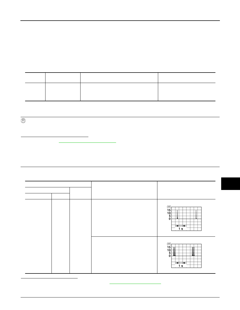
CHECK INSIDE KEY ANTENNA INPUT SIGNAL 1
1.
Turn ignition switch OFF.
2.
Check signal between BCM harness connector and ground with oscilloscope.
Is the inspection result normal?
YES
>> Check intermittent incident. Refer to
GI-38, "Intermittent Incident"
.
NO
>> GO TO 2.
2.
CHECK INSIDE KEY ANTENNA CIRCUIT
DTC No.
Trouble diagnosis
name
DTC detecting condition
Possible cause
B2621
INSIDE ANTENNA 1
CIRCUIT
An excessive high or low voltage from inside anten-
na is sent to BCM.
• Inside key antenna (instrument
center)
• Between BCM and Inside key an-
tenna (instrument center)
Terminals
Condition
Signal
(Reference value)
(+)
(–)
BCM connector
Terminal
M122
79
Ground
When Intelligent Key is in the passenger
compartment.
When Intelligent Key is not in the passen-
ger compartment.
JMKIA0062GB
JMKIA0063GB
DLK-60
< COMPONENT DIAGNOSIS >
[INTELLIGENT KEY SYSTEM]
B2621 INSIDE KEY ANTENNA 1
1.
Disconnect BCM connector and inside key antenna (instrument center) connector.
2.
Check continuity between BCM harness connector and inside key antenna (instrument center) connector.
3.
Check continuity between BCM harness connector and ground.
Is the inspection result normal?
YES
>> GO TO 3.
NO
>> Repair or replace harness between BCM and inside key antenna (instrument center).
3.
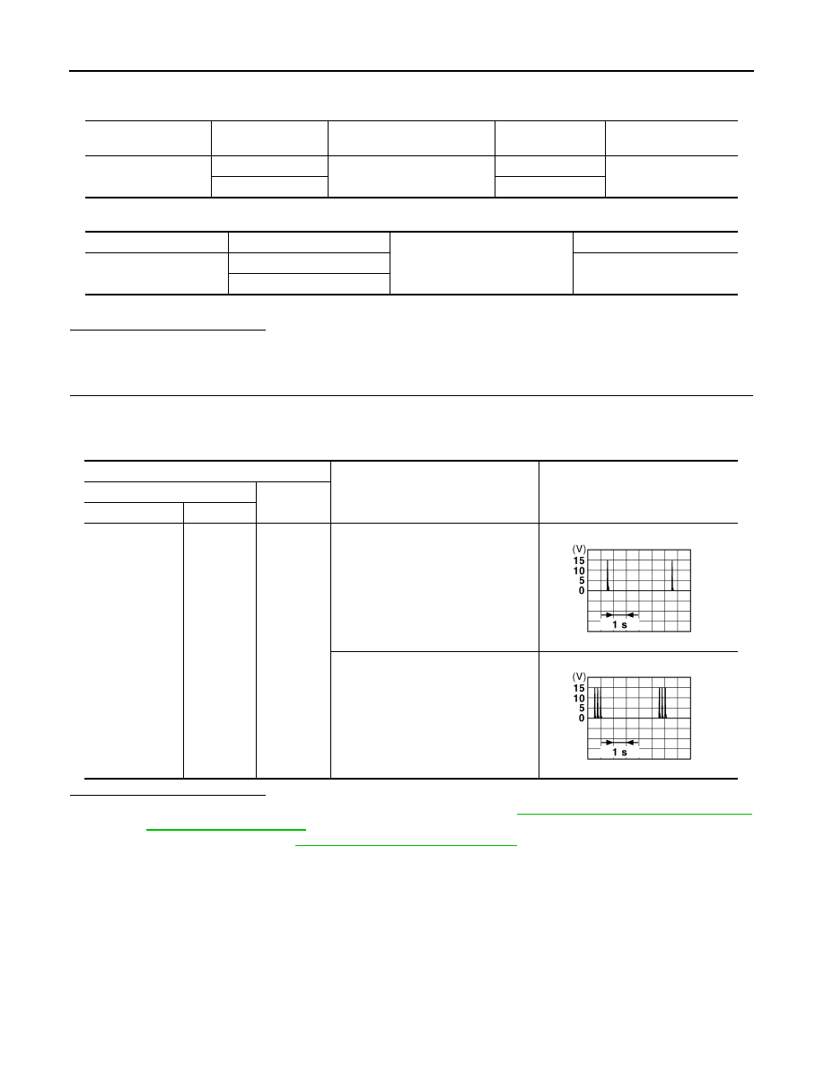
CHECK INSIDE KEY ANTENNA INPUT SIGNAL 2
1.
Replace inside key antenna (instrument center). (New antenna or other antenna)
2.
Connect BCM connector and inside key antenna (instrument center) connector.
3.
Check signal between BCM harness connector and ground with oscilloscope.
Is the inspection result normal?
YES
>> Replace inside key antenna (instrument center). Refer to
NO
>> Replace BCM. Refer to
BCS-79, "Removal and Installation"
BCM connector
Terminal
Inside key antenna
(Instrument center) connector
Terminal
Continuity
M122
78
M131
2
Existed
79
1
BCM connector
Terminal
Ground
Continuity
M122
78
Not existed
79
Terminals
Condition
Signal
(Reference value)
(+)
(–)
BCM connector
Terminal
M122
79
Ground
When Intelligent Key is in the passen-
ger compartment.
When Intelligent Key is not in the pas-
senger compartment.
JMKIA0062GB
JMKIA0063GB
Нет комментариевНе стесняйтесь поделиться с нами вашим ценным мнением.
Текст