Infiniti G37 Coupe. Manual — part 1046
POWER SUPPLY AND GROUND CIRCUIT
RF-9
< COMPONENT DIAGNOSIS >
C
D
E
F
G
H
I
J
L
M
A
B
RF
N
O
P
COMPONENT DIAGNOSIS
POWER SUPPLY AND GROUND CIRCUIT
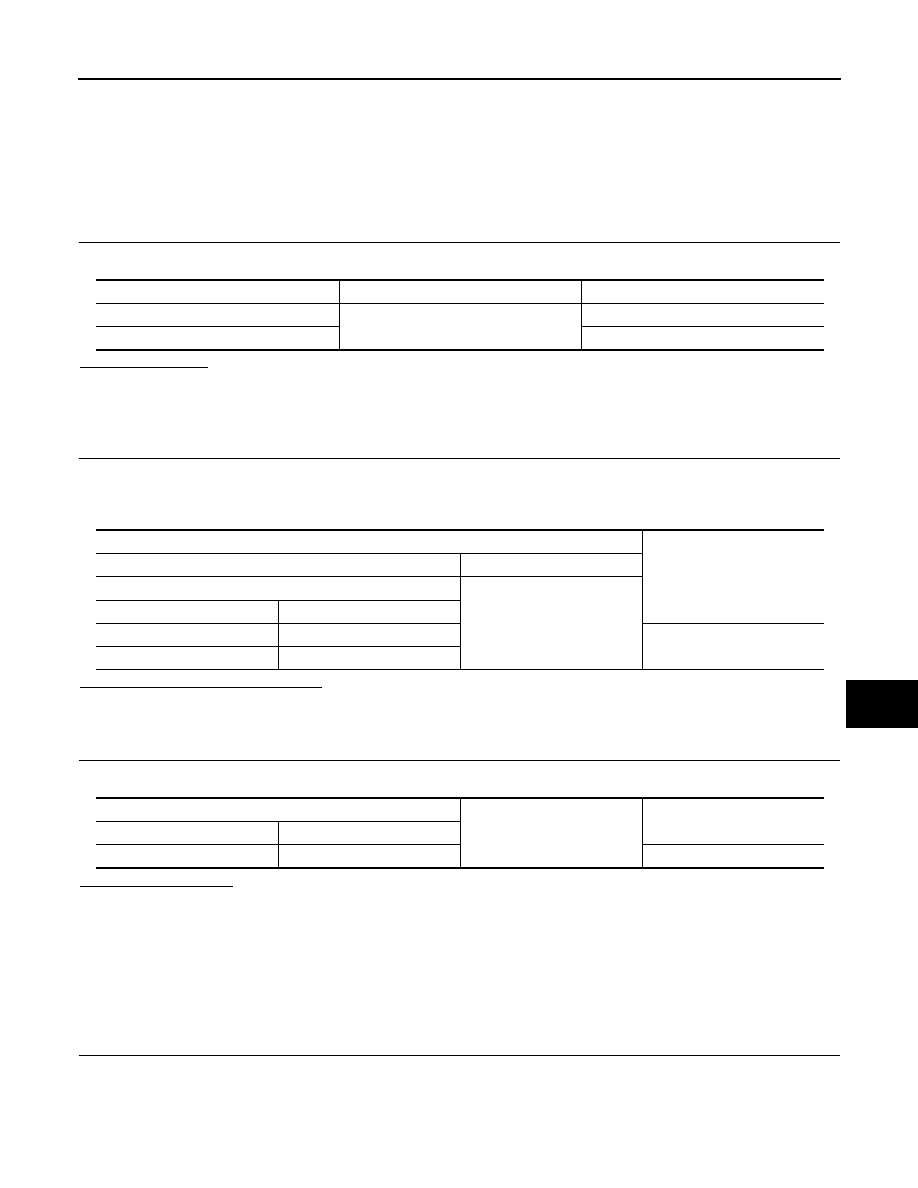
BCM
BCM : Diagnosis Procedure
INFOID:0000000001726781
1.
CHECK FUSE AND FUSIBLE LINK
Check that the following fuse and fusible link are not blown.
Is the fuse fusing?
YES
>> Replace the blown fuse or fusible link after repairing the affected circuit if a fuse or fusible link is
blown.
NO
>> GO TO 2.
2.
CHECK POWER SUPPLY CIRCUIT
1.
Turn ignition switch OFF.
2.
Disconnect BCM connectors.
3.
Check voltage between BCM harness connector and ground.
Is the measurement value normal?
YES
>> GO TO 3.
NO
>> Repair the harness or connector.
3.
CHECK GROUND CIRCUIT
Check continuity between BCM harness connector and ground.
Does continuity exist?
YES
>> INSPECTION END
NO
>> Repair the harness or connector.
SUNROOF MOTOR ASSEMBLY
SUNROOF MOTOR ASSEMBLY : Diagnosis Procedure
INFOID:0000000001722662
SUNROOF MOTOR ASSEMBLY
1.
CHECK POWER SUPPLY CIRCUIT
1.
Turn ignition switch OFF.
2.
Disconnect sunroof motor assembly connector.
3.
Turn ignition switch ON.
4.
Check voltage between sunroof motor assembly harness connector and ground.
Terminal No.
Signal name
Fuse and fusible link No.
1
Battery power supply
K
11
10
Terminals
Voltage
(Approx.)
(+)
(
−
)
BCM
Ground
Connector
Terminal
M118
1
Battery voltage
M119
11
BCM
Ground
Continuity
Connector
Terminal
M119
13
Existed

R F - 1 0
< COMPONENT DIAGNOSIS >
POWER SUPPLY AND GROUND CIRCUIT
Is the inspection result normal?
YES
>> GO TO 2.
NO
>> GO TO 3.
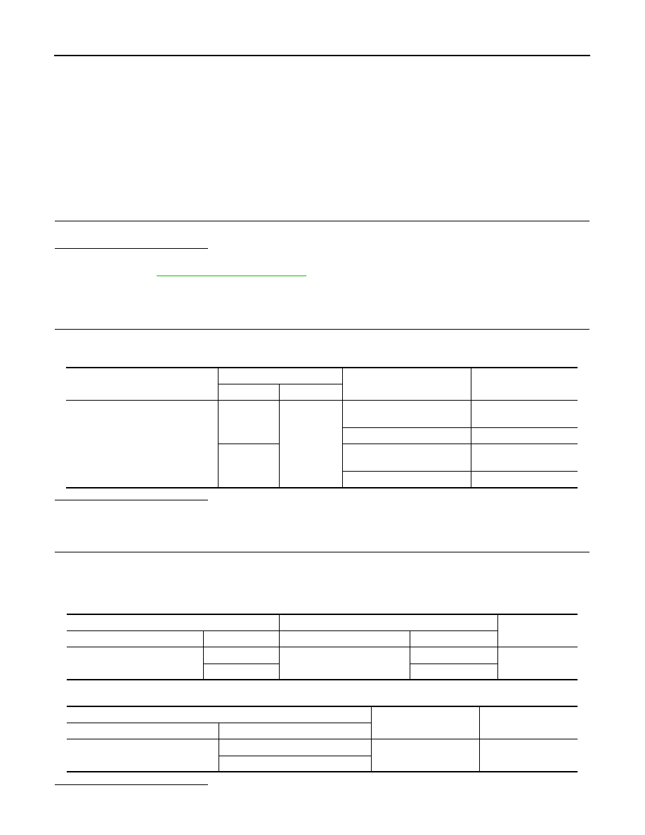
2.
CHECK GROUND CIRCUIT
1.
Turn ignition switch OFF.
2.
Check continuity between sunroof motor assembly harness connector and ground.
Is the inspection result normal?
YES
>> GO TO 5.
NO
>> Repair or replace the harness.
3.
CHECK SUNROOF MOTOR CIRCUIT
1.
Turn ignition switch OFF.
2.
Disconnect BCM connector.
3.
Check continuity between BCM harness connector and sunroof motor assembly harness connector.
4.
Check continuity between BCM harness connector and ground.
Is the inspection result normal?
YES
>> GO TO 4.
NO
>> Repair or replace the harness.
4.
CHECK BCM OUTPUT SIGNAL
1.
Connect BCM connector.
2.
Turn ignition switch ON.
3.
Check voltage between BCM harness connector and ground.
Is the inspection result normal?
YES
>> GO TO 5.
NO
>> Replace BCM. Refer to
5.
CHECK INTERMITTENT INCIDENT
Sunroof motor assembly
Ground
Voltage (V)
(Approx.)
Connector
Terminal
R4
7
Ground
Battery voltage
9
Sunroof motor assembly
Ground
Continuity
Connector
Terminal
R4
10
Ground
Existed
BCM
Sunroof motor assembly
Continuity
Connector
Terminal
Connector
Terminal
M118
2
R4
7
Existed
3
9
BCM
Ground
Continuity
Connector
Terminal
M118
2
Ground
Not existed
3
BCM
Ground
Voltage (V)
(Approx.)
Connector
Terminal
M118
2
Ground
Battery voltage
3
POWER SUPPLY AND GROUND CIRCUIT
RF-11
< COMPONENT DIAGNOSIS >
C
D
E
F
G
H
I
J
L
M
A
B
RF
N
O
P
GI-38, "Intermittent Incident"
.
>> INSPECTION END
RF-12
< COMPONENT DIAGNOSIS >
SUNROOF SWITCH
SUNROOF SWITCH
Description
INFOID:0000000001722639
• BCM supplies power.
• Sunroof motor assembly is sunroof motor and CPU integrated type.
• Tilts up/down & slides open/close by sunroof switch operation.
• In order to close sunroof lid certainly with the signal from unified meter and A/C amp. at the time of high
speed run, the sunroof motor torque at the time of tilt-down operation is controlled.
Component Function Check
INFOID:0000000001722640
1.
CHECK SUNROOF MOTOR FUNCTION
Check tilt up/down & slide open/close operations with sunroof switch.
Is the inspection result normal?
YES
>> Sunroof motor function is OK.
NO
>> Refer to
.
Diagnosis Procedure
INFOID:0000000001722641
1.
CHECK SUNROOF SWITCH INPUT SIGNAL
1.
Turn ignition switch ON.
2.
Check voltage between sunroof motor assembly harness connector and ground.
Is the inspection result normal?
YES
>> GO TO 4.
NO
>> GO TO 2.
2.
CHECK SUNROOF SWITCH CIRCUIT
1.
Turn ignition switch OFF.
2.
Disconnect sunroof motor assembly connector and sunroof switch connector.
3.
Check continuity between sunroof motor assembly harness connector and sunroof switch harness con-
nector.
4.
Check continuity between sunroof motor assembly harness connector and ground.
Is the inspection result normal?
YES
>> GO TO 3.
Sunroof motor assembly connector
Terminals
Condition
Voltage (V)
(Approx.)
(+)
(–)
R4
5
Ground
Sunroof switch is operated
TILT DOWN or SLIDE OPEN
0
Other than above
Battery voltage
1
Sunroof switch is operated
TILT UP or SLIDE CLOSE
0
Other than above
Battery voltage
Sunroof motor assembly
Sunroof switch
Continuity
Connector
Terminal
Connector
Terminal
R4
5
R16
1
Existed
1
3
Sunroof motor assembly
Ground
Continuity
Connector
Terminal
R4
5
Ground
Not existed
1
Нет комментариевНе стесняйтесь поделиться с нами вашим ценным мнением.
Текст