Infiniti G37 Coupe. Manual — part 750
HA-46
< ON-VEHICLE REPAIR >
LOW-PRESSURE PIPE 1 AND HIGH-PRESSURE PIPE 2
LOW-PRESSURE PIPE 1 AND HIGH-PRESSURE PIPE 2
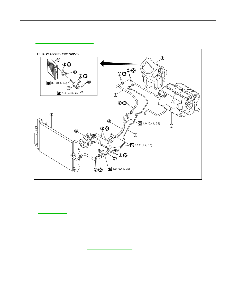
Exploded View
INFOID:0000000001713750
HA-13, "Refrigerant Connection"
.
Removal and Installation
INFOID:0000000001675644
REMOVAL
1.
Set the temperature at 18
°
C (60
°
F). Then disconnect the battery cable from the negative terminal.
2.
Use a refrigerant collecting equipment (for HFC-134a) to discharge the refrigerant.
3.
Remove cowl top cover. Refer to
.
1.
Blower unit
2.
O-ring
3.
Low-pressure pipe 2
4.
Low-pressure flexible hose
5.
Compressor
6.
Radiator & condenser assembly
7.
High-pressure flexible hose
8.
High-pressure pipe 1
9.
Heater & cooling unit assembly
10. Expansion valve
11.
Evaporator
12. High-pressure pipe 2
13. Low-pressure pipe 1
Refer to
for symbols in the figure.
JSIIA0109GB

LOW-PRESSURE PIPE 1 AND HIGH-PRESSURE PIPE 2
HA-47
< ON-VEHICLE REPAIR >
C
D
E
F
G
H
J
K
L
M
A
B
HA
N
O
P
4.
Disconnect one-touch joint between low-pressure pipe 1 (1) and
low-pressure pipe 2 (2) with disconnector (A) (SST:
9253089916).
CAUTION:
Cap or wrap the joint of the A/C piping with suitable mate-
rial such as vinyl tape to avoid the entry of air.
5.
Disconnect one-touch joints between high-pressure pipe 1 (3)
and high-pressure pipe 2 (4) with disconnector (SST:
9253089908).
CAUTION:
Cap or wrap the joint of the A/C piping with suitable mate-
rial such as vinyl tape to avoid the entry of air.
6.
Remove foot grille (right). Refer to
7.
Remove blower unit. Refer to
8.
Remove air mix door motor (passenger side). Refer to
.
9.
Remove mode door motor. Refer to
.
10. Remove main link (right) and max. cool door link (right). Refer to
.
11. Remove mounting screws (A), and then remove evaporator
cover (1).
12. Remove mounting bolt (A), and then remove low-pressure pipe
1 (1) and high-pressure pipe 2 (2).
CAUTION:
Cap or wrap the joint of the A/C piping and expansion valve
with suitable material such as vinyl tape to avoid the entry
of air.
INSTALLATION
Installation is basically the reverse order of removal.
CAUTION:
• Replace O-rings with new ones. Then apply compressor oil to them when installing.
• Female-side piping connection is thin and easy to deform. Slowly insert the male-side piping
straight in axial direction.
• Insert piping securely until a click is heard.
• After piping connection is completed, pull male-side piping by hand to make sure that connection
does not come loose.
• Check for leakages when recharging refrigerant.
JSIIA0037ZZ
JSIIA0093ZZ
JSIIA0029ZZ

HA-48
< ON-VEHICLE REPAIR >
CONDENSER
CONDENSER
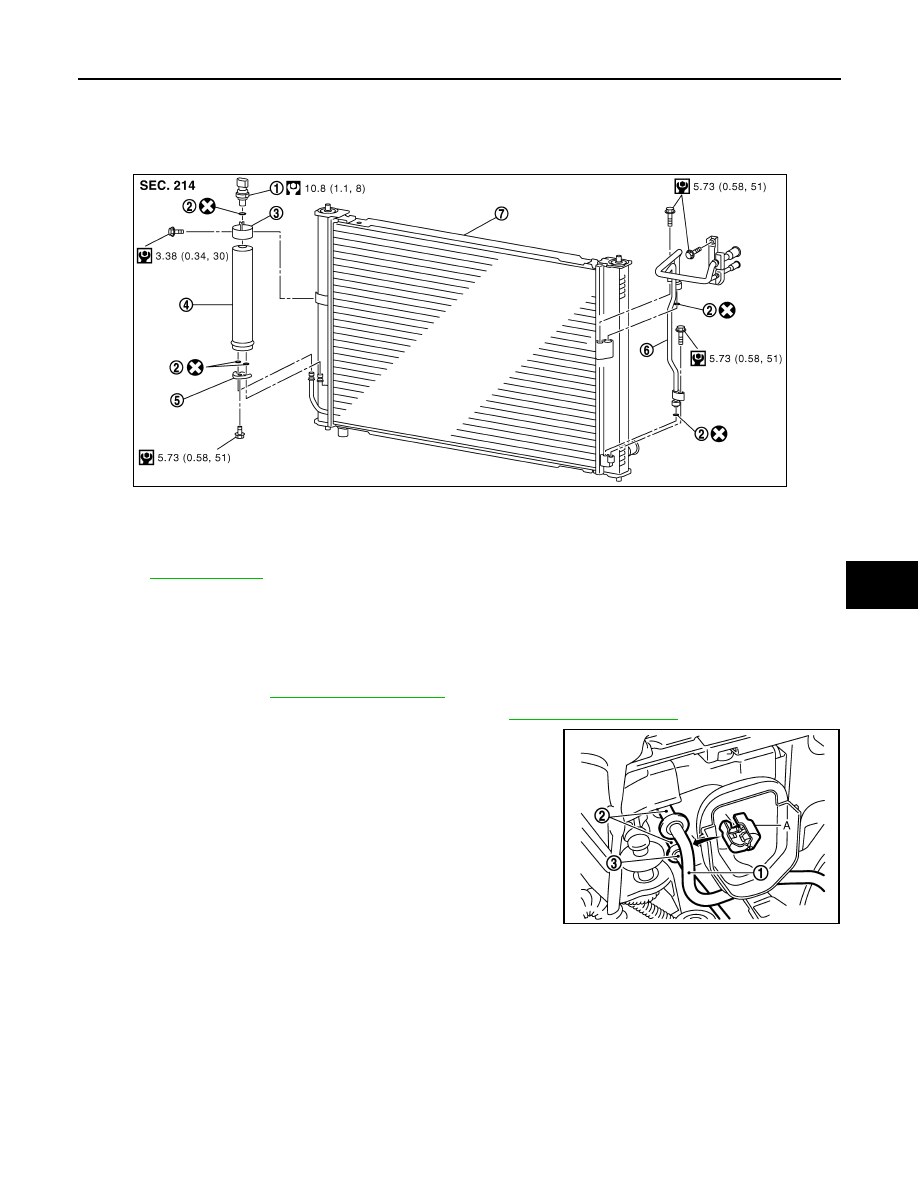
Exploded View
INFOID:0000000001675645
Removal and Installation
INFOID:0000000001675646
REMOVAL
1.
Use a refrigerant collecting equipment (for HFC-134a) to discharge the refrigerant.
2.
Remove radiator & condenser assembly. Refer to
CAUTION:
Be careful not to damage core surface of radiator & condenser assembly/
INSTALLATION
Installation is basically the reverse order of removal.
CAUTION:
• Replace O-rings with new ones. Then apply compressor oil to them when installing.
• Female-side piping connection is thin and easy to deform. Slowly insert the male-side piping
straight in axial direction.
• Insert piping securely until a click is heard.
• After piping connection is completed, pull male-side piping by hand to make sure that connection
does not come loose.
• Check for leakages when recharging refrigerant.
1.
Refrigerant pressure sensor
2.
O-ring
3.
Liquid tank bracket
4.
Liquid tank
5.
Bracket
6.
Condenser pipe assembly
7.
Radiator & condenser assembly
Refer to
for symbols in the figure.
JSIIA0012GB
CONDENSER PIPE ASSEMBLY
HA-49
< ON-VEHICLE REPAIR >
C
D
E
F
G
H
J
K
L
M
A
B
HA
N
O
P
CONDENSER PIPE ASSEMBLY
Exploded View
INFOID:0000000001713753
Removal and Installation
INFOID:0000000001675648
REMOVAL
1.
Use a refrigerant collecting equipment (for HFC-134a) to discharge the refrigerant.
2.
Remove front bumper.
.
3.
Remove air cleaner case (LH) and air duct (LH). Refer to
.
4.
Disconnect one-touch joint between high-pressure flexible hose
(1) and condenser pipe assembly (2) with disconnector (A)
(SST: 9253089912).
CAUTION:
Cap or wrap the joint of the A/C piping with suitable mate-
rial such as vinyl tape to avoid the entry of air.
5.
Disconnect one-touch joints between high-pressure pipe 1 (3)
and condenser pipe assembly with disconnector (A) (SST:
9253089908).
CAUTION:
Cap or wrap the joint of the A/C piping with suitable mate-
rial such as vinyl tape to avoid the entry of air.
1.
Refrigerant pressure sensor
2.
O-ring
3.
Liquid tank bracket
4.
Liquid tank
5.
Bracket
6.
Condenser pipe assembly
7.
Radiator & condenser assembly
Refer to
JSIIA0012GB
JSIIA0095ZZ
Нет комментариевНе стесняйтесь поделиться с нами вашим ценным мнением.
Текст