Infiniti G37 Coupe. Manual — part 94

AV
MULTI AV SYSTEM
AV-129
< FUNCTION DIAGNOSIS >
[BOSE AUDIO WITHOUT NAVIGATION]
C
D
E
F
G
H
I
J
K
L
M
B
A
O
P
TEL ADAPTER UNIT
• Inputs the TEL voice signal from TEL antenna and outputs it to the AV control
unit.
• It is connected with the AV control unit via AV communication and controlled
with the AV control unit.
TEL ANTENNA
Receives the TEL voice signal and outputs it to the TEL adapter unit.
SATELLITE RADIO TUNER
• Inputs the satellite radio signal from satellite radio antenna and outputs the
sound signal to the AV control unit.
• It is controlled with the AV control unit and serial communication (communica-
tion signal and request signal).
SATELLITE RADIO ANTENNA
Receives the satellite radio signal and outputs it to the satellite radio tuner.
iPod ADAPTER
• Inputs iPod sound signal from iPod
®
, and outputs iPod sound signal to AV con-
trol unit.
• Receiving/transmitting of iPod
®
operation signals are performed as follows:
- between AV control unit and iPod adapter: AV communication.
- between iPod
®
and iPod adapter: serial communication.
Part name
Description
AV-130
< FUNCTION DIAGNOSIS >
[BOSE AUDIO WITHOUT NAVIGATION]
AUDIO SYSTEM
AUDIO SYSTEM
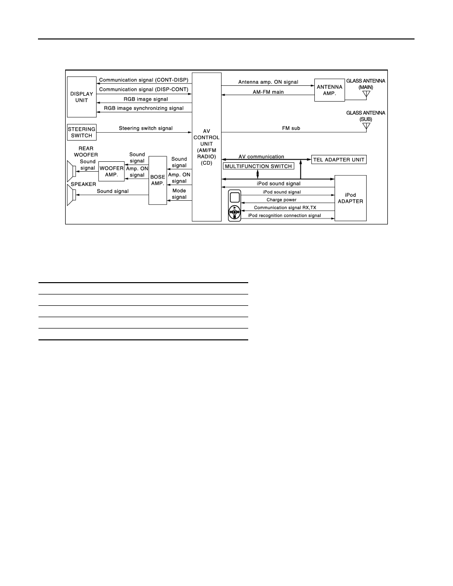
System Diagram
INFOID:0000000001558987
System Description
INFOID:0000000001558988
The audio system is equipped with the following functions. Each function can be operated with the multifunc-
tion switch, preset switch or steering switch. It indicates the operation status of AUDIO to the display.
FUNCTION DESCRIPTION
Operating signal
Operation of the audio system can be performed with the multifunction switch, preset switch or steering
switch.
• Operating signal is transmitted to AV control unit with AV communication when it is operated by multifunction
switch or preset switch. The CD ejection operating signal is performed by hardwire.
• Operating signal is transmitted to AV control unit with steering switch signal when it is operated by steering
switch.
Screen display
• The display switching of the screen is performed with the communication signal between the display and the
AV control unit.
• The image signal to display operating condition is performed with RGB signal, RGB area signal and RGB
image synchronizing signal.
AM/FM Radio Mode
• AM/FM radio tuner is built into AV control unit.
• Audio signal is received by glass antenna, next it is amplified by antenna amp, and finally it is input to AV
control unit. Audio signal is input to BOSE amp. and BOSE amp. outputs to woofer amp. and each speaker
for AV control unit.
CD Mode
• CD function is built into AV control unit.
• AV control unit outputs audio signal to BOSE amp. and BOSE amp. outputs to woofer amp. and each
speaker when CD is inserted to AV control unit.
iPod Connection
JSNIA0563GB
Function
AM/FM radio
CD
iPod connection
Driver's Audio Stage
AV
AUDIO SYSTEM
AV-131
< FUNCTION DIAGNOSIS >
[BOSE AUDIO WITHOUT NAVIGATION]
C
D
E
F
G
H
I
J
K
L
M
B
A
O
P
• Connect iPod
®
and iPod adapter with wire harness and iPod adapter input iPod sound signal from iPod
®
.
When iPod mode is selected, iPod adapter output iPod sound signal to AV control unit. AV control unit output
sound signal to BOSE amp., and BOSE amp. output sound signal to woofer amp. and each speaker.
• Receiving/transmitting of iPod
®
operation signals are performed as follows:
- between AV control unit and iPod adapter: AV communication.
- between iPod
®
and iPod adapter: serial communication.
• The iPod
®
connection status can be recognized whether iPod adapter receives iPod connection recognition
signal.
• The iPod adapter is possible to charge iPod
®
.
Driver's Audio Stage Mode
• Driver's Audio Stage controls the speaker's output characteristic by BOSE amp. so that the driver's seat is to
be the center of sounds.
• ON/OFF signals of Driver's Audio Stage are transmitted from AV control unit to BOSE amp. using Mode sig-
nal.
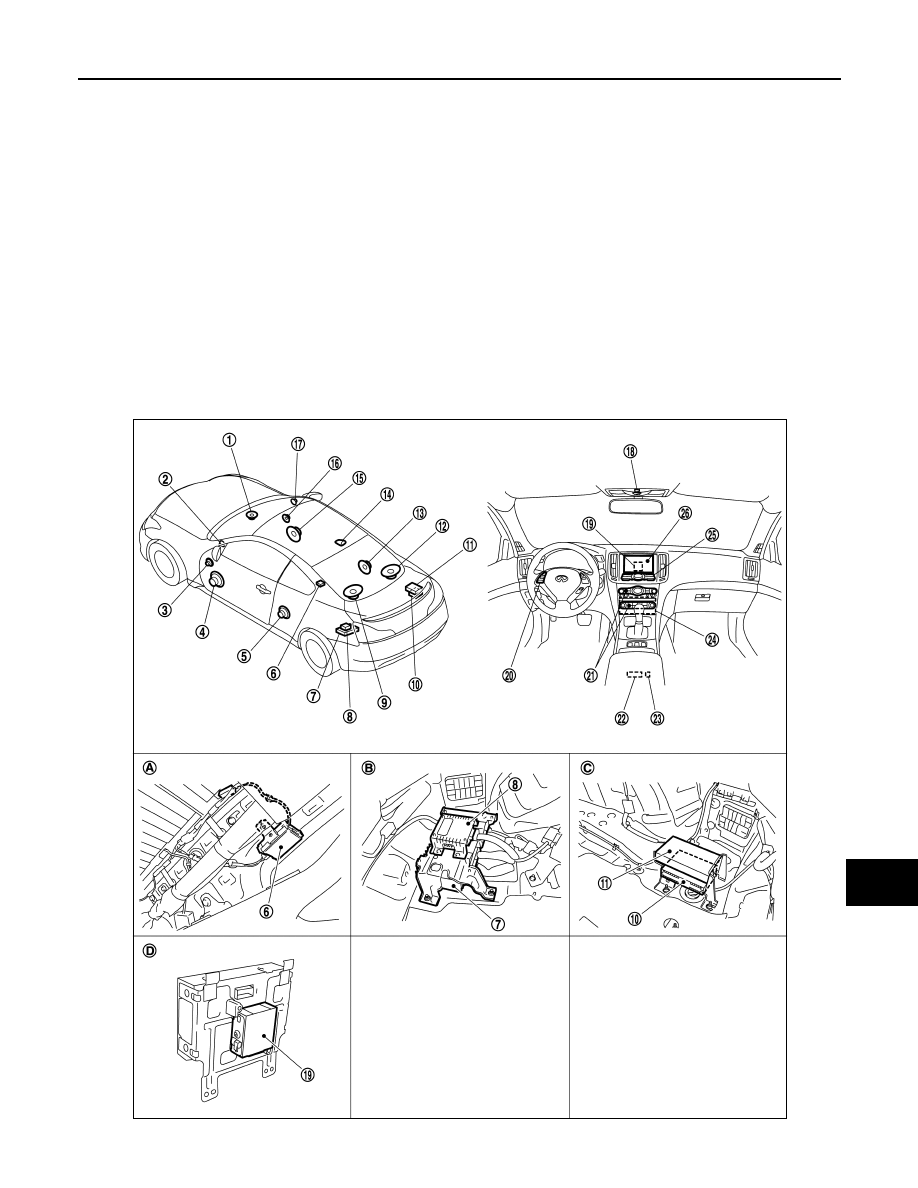
Component Parts Location
INFOID:0000000001682964
JPNIA0467ZZ

AV-132
< FUNCTION DIAGNOSIS >
[BOSE AUDIO WITHOUT NAVIGATION]
AUDIO SYSTEM
Component Description
INFOID:0000000001558990
1.
Center speaker
2.
Tweeter LH
3.
Door squawker LH
4.
Door woofer LH
5.
Rear speaker LH
6.
Antenna amp.
7.
BOSE amp.
8.
Woofer amp.
9.
Rear woofer LH
10. Satellite radio tuner
11. TEL adapter unit
12. Rear woofer RH
13. Rear speaker RH
14. Satellite radio antenna
15. Door woofer RH
16. Door squawker RH
17. Tweeter RH
18. Microphone
19. iPod adapter
20. Steering switch
21. Preset switch
22. Auxiliary input jacks
23. iPod connector
24. AV control unit
25. Multifunction switch
26. Display unit
A.
Within rear pillar finisher LH
B.
Trunk room LH
C.
Trunk room RH
D.
Rear view of the display
Part name
Description
AV CONTROL UNIT
• The AM/FM receiving function and the CD playing function are equipped.
• Audio signal is output to BOSE amp. from each function.
DISPLAY UNIT
• Display image is controlled by the serial communication from AV control unit.
• RGB image signal (audio operation condition) is input from AV control unit.
BOSE AMP.
Inputs power (amp ON) and sound signal from AV control unit, and outputs sound
signal to woofer amp. and each speaker.
WOOFER AMP.
Inputs power (amp ON) and sound signal from BOSE amp., and outputs sound
signal to rear woofer.
DOOR WOOFER
• Outputs sound signal from BOSE amp.
• Outputs low-pitched sound.
DOOR SQUAWKER
• Outputs sound signal from BOSE amp.
• Outputs midrange sound.
REAR SPEAKER
• Outputs sound signal from BOSE amp.
• Outputs high, mid and low range sounds.
TWEETER
• Outputs sound signal from BOSE amp.
• Outputs high range sound.
CENTER SPEAKER
• Outputs sound signal from BOSE amp.
• Outputs high, mid and low range sounds.
REAR WOOFER
• Outputs sound signal from woofer amp.
• Outputs low-pitched sound.
MULTIFUNCTION SWITCH
• Each audio operation can be operated.
• Connected with AV control unit via cable, and operation signal is transmitted to
AV control unit via AV communication.
PRESET SWITCH
• Each audio operation can be operated.
• It is connected to the multifunction switch by AV communication. The operation
signal is transmitted to the AV control unit.
• The CD ejection operating signal is performed by hardwire.
STEERING SWITCH
• Each audio operation can be operated.
• Steering switch signal (operation signal) is output to AV control unit.
ANTENNA AMP.
• Radio signal received by glass antenna is amplified and transmitted to AV con-
trol unit.
• Power (antenna amp ON signal) is supplied from AV control unit.
iPod ADAPTER
• Inputs iPod sound signal from iPod
®
, and outputs iPod sound signal to AV con-
trol unit.
• Receiving/transmitting of iPod
©
operation signals are performed as follows:
- between AV control unit and iPod adapter: AV communication.
- between iPod
®
and iPod adapter: serial communication.
Нет комментариевНе стесняйтесь поделиться с нами вашим ценным мнением.
Текст