Infiniti G37 Coupe. Manual — part 1306

DIAGNOSIS AND REPAIR WORK FLOW
TM-77
< BASIC INSPECTION >
[5AT: RE5R05A]
C
E
F
G
H
I
J
K
L
M
A
B
TM
N
O
P
>> GO TO 3.
3.
CHECK DTC
1.
Check DTC.
2.
Perform the following procedure if DTC is detected.
• Record DTC.
• Erase DTC. Refer to
TM-108, "Diagnosis Description"
.
Is any DTC detected?
YES
>> GO TO 4.
NO
>> GO TO 6.
4.
PERFORM DIAGNOSTIC PROCEDURE
Perform “Diagnosis Procedure” for the displayed DTC.
>> GO TO 5.
5.
PERFORM DTC CONFIRMATION PROCEDURE
Perform “DTC CONFIRMATION PROCEDURE” for the displayed DTC.
Is any DTC detected?
YES
>> GO TO 4.
NO
>> GO TO 6.
6.
CHECK SYMPTOM 2
Try to confirm the symptom described by the customer.
Is any malfunction present?
YES
>> GO TO 7.
NO
>> INSPECTION END
7.
ROAD TEST
Perform “ROAD TEST”. Refer to
.
>> GO TO 8.
8.
CHECK SYMPTOM 3
Try to confirm the symptom described by the customer.
Is any malfunction present?
YES
>> GO TO 2.
NO
>> INSPECTION END
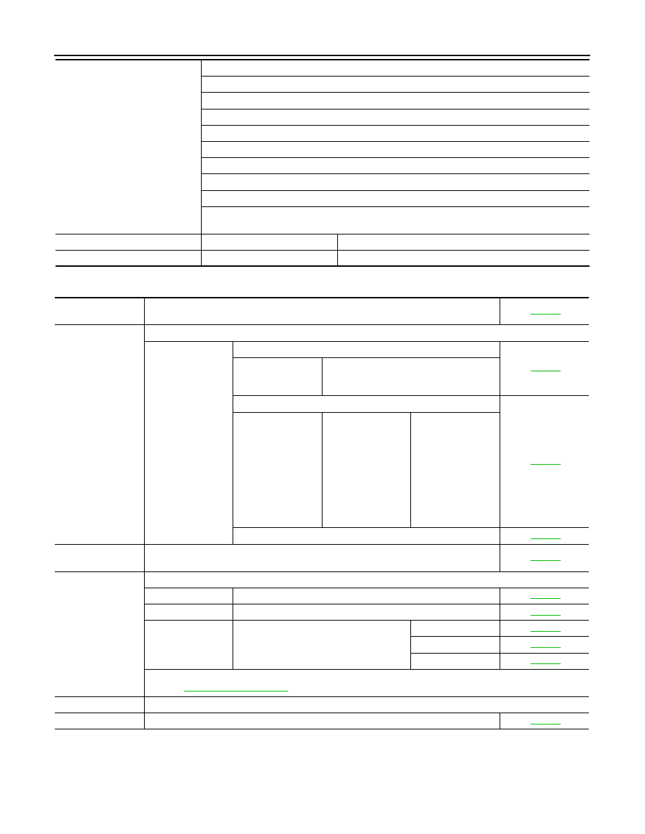
Diagnostic Work Sheet
INFOID:0000000001672104
INFORMATION FROM CUSTOMER
KEY POINTS
• WHAT. . Vehicle and A/T model
• WHEN. . Date, Frequencies
• WHERE. . Road conditions
• HOW. . Operating conditions, Symptoms
Customer name
MR/MS
Model and Year
VIN
Trans. Model
Engine
Mileage
Malfunction Date
Manuf. Date
In Service Date
Frequency
❏
Continuous
❏
Intermittent (
times a day)
TM-78
< BASIC INSPECTION >
[5AT: RE5R05A]
DIAGNOSIS AND REPAIR WORK FLOW
DIAGNOSTIC WORK SHEET
Symptoms
❏
Vehicle does not move.
(
❏
Any position
❏
Particular position)
❏
No up-shift
(
❏
1st
→
2nd
❏
2nd
→
3rd
❏
3rd
→
4th
❏
4th
→
5th)
❏
No down-shift
(
❏
5th
→
4th
❏
4th
→
3rd
❏
3rd
→
2nd
❏
2nd
→
1st)
❏
Lock-up malfunction
❏
Shift point too high or too low.
❏
Shift shock or slip
(
❏
N
→
D
❏
N
→
R
❏
Lock-up
❏
Any drive position)
❏
Noise or vibration
❏
No kick down
❏
No pattern select
❏
Others
(
)
A/T CHECK indicator lamp
❏
Continuously lit
❏
Not lit
Malfunction indicator lamp (MIL)
❏
Continuously lit
❏
Not lit
1
❏
Read the item on cautions concerning fail-safe and understand the customer's com-
plaint.
2
❏
A/T fluid inspection, stall test and line pressure test
❏
A/T fluid inspection
❏
Leak (Repair leak location.)
❏
State
❏
Amount
❏
Stall test
❏
Torque converter
one-way clutch
❏
Front brake
❏
High and low re-
verse clutch
❏
Low coast brake
❏
Forward brake
❏
Reverse brake
❏
Forward one-way
clutch
❏
1st one-way
clutch
❏
3rd one-way
clutch
❏
Engine
❏
Line pressure low
❏
Except for input
clutch and direct
clutch, clutches and
brakes OK
❏
Line pressure test - Suspected part:
3
❏
Perform self-diagnosis. — Check detected items to repair or replace malfunctioning
part.
4
❏
Perform road test.
5-1
❏
Check before engine is started
5-2
❏
Check at idle
5-3
Cruise test
❏
Part 1
❏
Part 2
❏
Part 3
❏
Check malfunction phenomena to repair or replace malfunctioning part after completing all road tests.
5
❏
Drive vehicle to check that the malfunction phenomenon has been resolved.
6
❏
Erase the results of the self-diagnosis from the TCM and the ECM.
A/T CONTROL SYSTEM
TM-79
< FUNCTION DIAGNOSIS >
[5AT: RE5R05A]
C
E
F
G
H
I
J
K
L
M
A
B
TM
N
O
P
FUNCTION DIAGNOSIS
A/T CONTROL SYSTEM
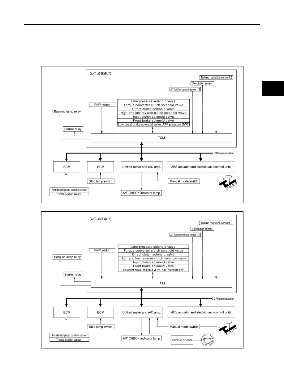
System Diagram
INFOID:0000000001672105
Without Paddle Shifter
With Paddle Shifter
JSDIA0122GB
JPDIA0049GB
TM-80
< FUNCTION DIAGNOSIS >
[5AT: RE5R05A]
A/T CONTROL SYSTEM
System Description
INFOID:0000000001672106
The A/T senses vehicle operating conditions through various sensors or signals. It always controls the opti-
mum shift position and reduces shifting and lock-up shocks.
TCM FUNCTION
The function of the TCM is to:
• Receive input signals transmitted from various switches and sensors.
• Determine required line pressure, shifting point, lock-up operation, engine brake operation, etc.
• Transmit required output signals to the respective solenoids.
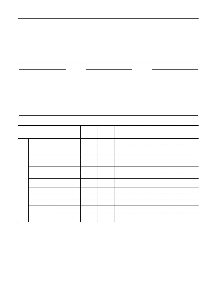
Input/Output Signal of TCM
SENSORS (or SIGNALS)
⇒
TCM
⇒
ACTUATORS
PNP switch
Accelerator pedal position signal
Closed throttle position signal
Wide open throttle position signal
Engine speed signal
A/T fluid temperature sensor
Revolution sensor
Vehicle speed signal
Manual mode switch signal
Stop lamp switch signal
Turbine revolution sensor
ATF pressure switch
Shift control
Line pressure control
Lock-up control
Engine brake control
Timing control
Fail-safe control
Self-diagnosis
CONSULT-III communication
line
Duet-EA control
CAN system
Input clutch solenoid valve
Direct clutch solenoid valve
Front brake solenoid valve
High and low reverse clutch sole-
noid valve
Low coast brake solenoid valve
Torque converter clutch solenoid
valve
Line pressure solenoid valve
A/T CHECK indicator lamp
Back-up lamp relay
Starter relay
Control item
Line
pressure
control
Vehicle
speed
control
Shift
control
Lock-up
control
Engine
brake
control
Fail-safe
function
*3
Self-diag-
nostics
function
Input
Accelerator pedal position signal
*5
X
X
X
X
X
X
X
Vehicle speed sensor A/T
(revolution sensor)
X
X
X
X
X
X
X
Vehicle speed sensor MTR
*1, *5
X
Closed throttle position signal
*5
X
*2
X
X
X
X
*4
Wide open throttle position signal
*5
X
X
*4
Turbine revolution sensor 1
X
X
X
X
X
Turbine revolution sensor 2
(for 4th speed only)
X
X
X
X
X
Engine speed signals
*5
X
X
X
X
X
X
X
Stop lamp switch signal
*5
X
X
X
X
*4
A/T fluid temperature sensors 1, 2
X
X
X
X
X
X
ASCD or ICC
sensor inte-
grated unit
Operation signal
*5
X
X
X
Overdrive cancel
signal
(*5)
X
Нет комментариевНе стесняйтесь поделиться с нами вашим ценным мнением.
Текст