Infiniti G37 Coupe. Manual — part 1291
REAR OIL SEAL
TM-17
< ON-VEHICLE REPAIR >
[6MT: FS6R31A]
C
E
F
G
H
I
J
K
L
M
A
B
TM
N
O
P
ON-VEHICLE REPAIR
REAR OIL SEAL
Exploded View
INFOID:0000000001732870
.
Removal and Installation
INFOID:0000000001732871
REMOVAL
1.
Remove propeller shaft assembly. Refer to
DLN-7, "Removal and Installation"
.
2.
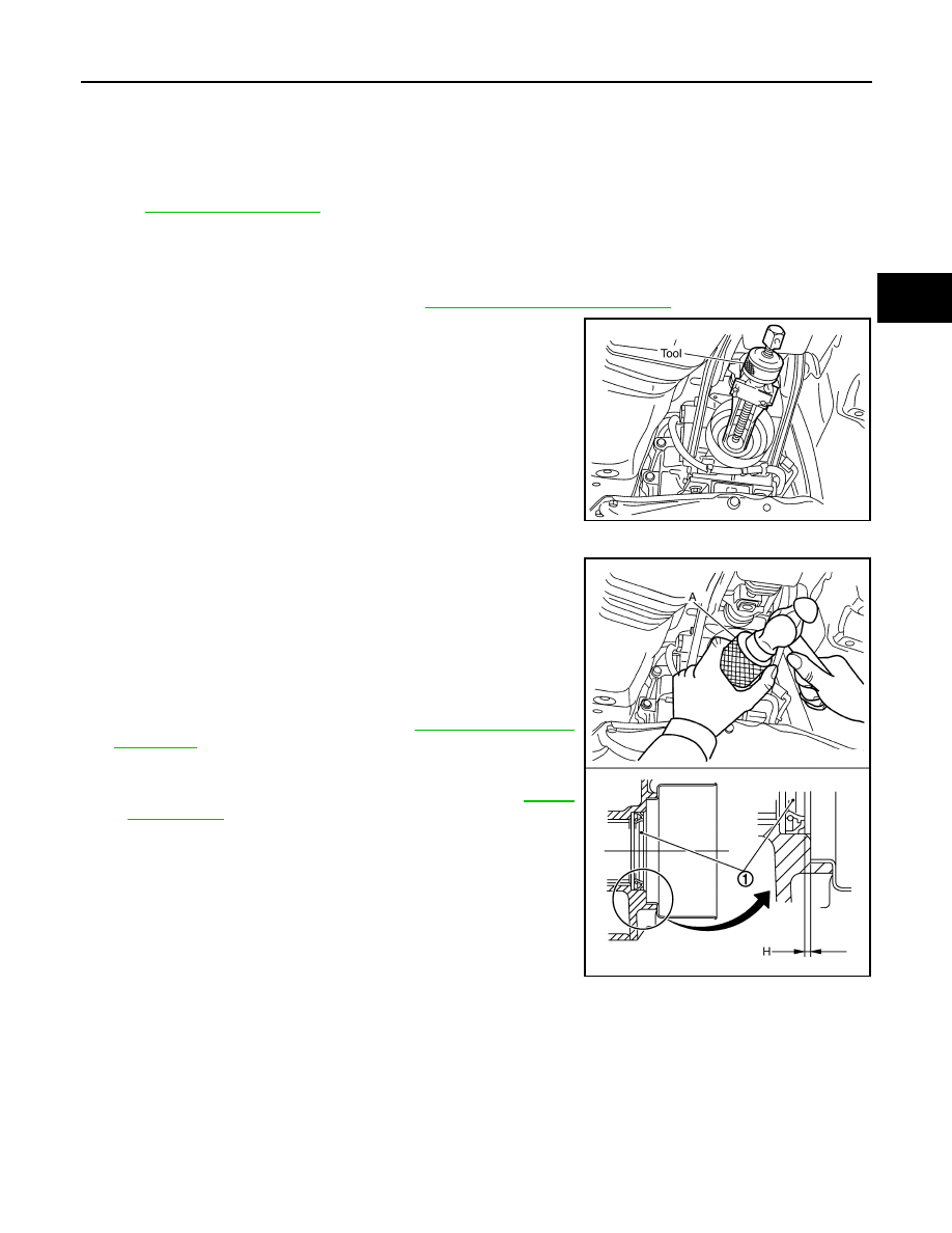
Remove rear oil seal using a puller [SST: KV381054S0 (J-
34286)].
INSTALLATION
1.
Apply multi-purpose grease to lip of rear oil seal (1). Drive in rear
oil seal to rear extension using the drift (A) [SST: ST33400001
(J-26082)].
CAUTION:
• Never reuse rear oil seal.
• When installing, never incline rear oil seal.
2.
Install propeller shaft assembly. Refer to
.
CAUTION:
• If lubricant leak has occurred during the repair work,
check oil level after finishing work. Refer to
.
PCIB0194E
Dimension “H”
: 1.2 - 2.2 mm (0.047 - 0.087 in)
JPDIC0032ZZ
TM-18
< ON-VEHICLE REPAIR >
[6MT: FS6R31A]
SHIFT CONTROL
SHIFT CONTROL
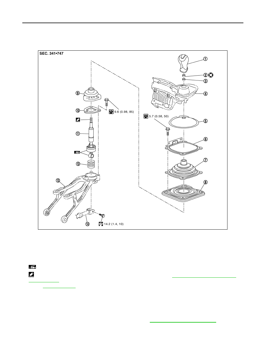
Exploded View
INFOID:0000000001732872
Removal and Installation
INFOID:0000000001732873
REMOVAL
1.
Remove shift knob with the following procedure.
a.
Release metal clips on console finisher assembly. Refer to
IP-24, "Removal and Installation"
.
1.
Shift knob
2.
Insulator
3.
Seat
4.
Console finisher assembly
5.
Felt
6.
Hole cover
7.
Control lever boot B
8.
Hole insulator
9.
Control lever boot A
10. Guide plate
11.
Control lever assembly
12. Control lever spring
13. Control lever housing
14. Control rod
: Apply multi-purpose grease.
: Apply Genuine Medium Strength Thread Locking Sealant or an equivalent. Refer to
GI-15, "Recommended Chemical Prod-
.
Refer to
for symbols not described on the above.
JPDIC0342GB

SHIFT CONTROL
TM-19
< ON-VEHICLE REPAIR >
[6MT: FS6R31A]
C
E
F
G
H
I
J
K
L
M
A
B
TM
N
O
P
b.
Lift console finisher assembly and then set a suitable pliers to
control lever assembly.
CAUTION:
Put waste cloth (A) between a suitable pliers and control
lever assembly to avoid damaging control lever assembly.
c.
Set a suitable pliers to shift knob.
CAUTION:
Put waste cloth (A) between a suitable pliers and shift knob
to avoid damaging shift knob.
d.
Keeping control lever assembly in place with a suitable pliers,
loosen shift knob with a suitable pliers.
NOTE:
Remove shift knob from control lever assembly keeping a suit-
able pliers in place because a certain power to turn shift knob is
still necessary even after adhesive is peeled.
e.
Remove shift knob from control lever assembly.
2.
Remove insulator and seat from control lever assembly.
3.
Remove console finisher assembly.
4.
Remove center console assembly. Refer to
.
5.
Remove felt.
6.
Release boot from control lever housing. Then remove control
rod mounting bolt and then separate control lever assembly and
control rod.
JPDIC0002ZZ
JPDIC0003ZZ
JPDIC0004ZZ
JPDIC0005ZZ
SCIA2561J

TM-20
< ON-VEHICLE REPAIR >
[6MT: FS6R31A]
SHIFT CONTROL
7.
Remove hole cover mounting bolts and then remove hole cover.
8.
Remove control lever boot B and hole insulator.
9.
Remove control lever boot A.
10. Remove guide plate mounting bolts and then remove control
lever assembly and control lever spring from control lever hous-
ing.
CAUTION:
Restrain guide plate while doing this because there is a
danger control lever assembly will fly out of control lever
housing.
INSTALLATION
1.
Set control lever spring, control lever assembly, and guide plate to control lever housing and then tempo-
rarily tightening guide plate mounting bolts.
CAUTION:
Restrain guide plate while doing this because there is a danger control lever assembly will fly out
of control lever housing.
JPDIC0006ZZ
JPDIC0007ZZ
JPDIC0008ZZ
JPDIC0009ZZ
Нет комментариевНе стесняйтесь поделиться с нами вашим ценным мнением.
Текст