Infiniti Q45 (FY33). Manual — part 8
Control System
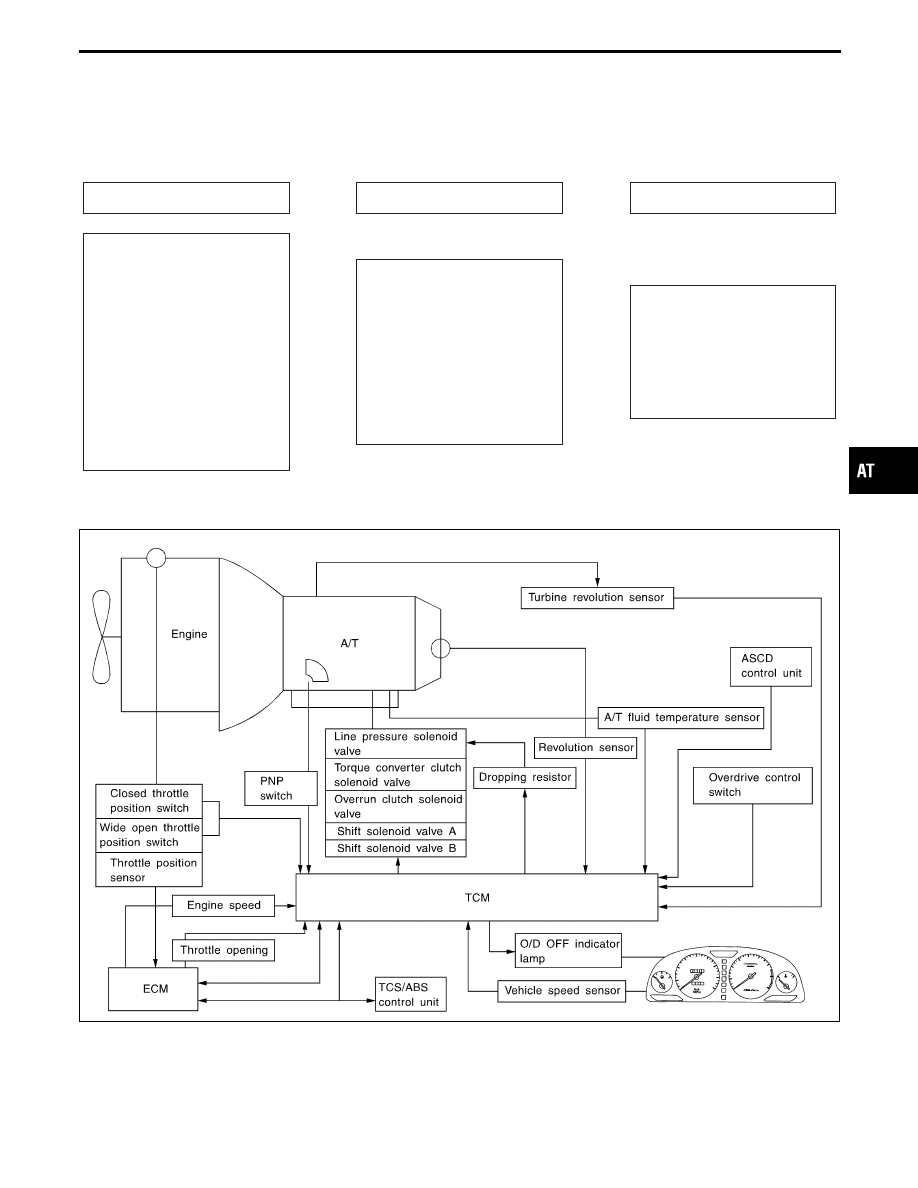
OUTLINE
The automatic transmission senses vehicle operating conditions through various sensors. It always controls
the optimum shift position and reduces shifting and lock-up shocks.
SENSORS
TCM
ACTUATORS
PNP switch
Throttle position sensor
Closed throttle position switch
Wide open throttle position
switch
Engine speed signal
A/T fluid temperature sensor
Revolution sensor
Vehicle speed sensor
Turbine revolution sensor
Overdrive control switch
ASCD control unit
TCS/ABS control unit
E
Shift control
Line pressure control
Lock-up control
Overrun clutch control
Timing control
Fail-safe control
Self-diagnosis
CONSULT-II communication line
control
Duet-EA control
E
Shift solenoid valve A
Shift solenoid valve B
Overrun clutch solenoid valve
Torque converter clutch
solenoid valve
Line pressure solenoid valve
O/D OFF indicator lamp
CONTROL SYSTEM
SAT741J
GI
MA
EM
LC
EC
FE
PD
FA
RA
BR
ST
RS
BT
HA
EL
IDX
OVERALL SYSTEM
AT-29

TCM FUNCTION
The function of the TCM is to:
I
Receive input signals sent from various switches and sensors.
I
Determine required line pressure, shifting point, lock-up operation, and engine brake operation.
I
Send required output signals to the respective solenoids.
INPUT/OUTPUT SIGNAL OF TCM
Sensors and solenoid valves
Function
Input
PNP switch
Detects select lever position and sends a signal to TCM.
Throttle position sensor
Detects throttle valve position and sends a signal to TCM.
Closed throttle position switch
Detects throttle valve’s fully-closed position and sends a signal to TCM.
Wide open throttle position switch
Detects a throttle valve position of greater than 1/2 of full throttle and sends a
signal to TCM.
Engine speed signal
From ECM.
A/T fluid temperature sensor
Detects transmission fluid temperature and sends a signal to TCM.
Revolution sensor
Detects output shaft rpm and sends a signal to TCM.
Turbine revolution sensor
Sends an input shaft revolution signal.
Vehicle speed sensor
Used as an auxiliary vehicle speed sensor. Sends a signal when revolution sen-
sor (installed on transmission) malfunctions.
Overdrive control switch
Sends a signal, which prohibits a shift to “D
4
” (overdrive) position, to the TCM.
ASCD control unit
Sends a cruise signal or “D
4
” (overdrive) cancel signal to TCM.
Output
Shift solenoid valve A/B
Selects shifting point suited to driving conditions in relation to a signal sent from
TCM.
Line pressure solenoid valve
Regulates (or decreases) line pressure suited to driving conditions in relation to
a signal sent from TCM.
Torque converter clutch solenoid valve
Regulates (or decreases) lock-up pressure suited to driving conditions in relation
to a signal sent from TCM.
Overrun clutch solenoid valve
Controls an “engine brake” effect suited to driving conditions in relation to a sig-
nal sent from TCM.
O/D OFF indicator lamp
Shows TCM faults, when A/T control components malfunction.
OVERALL SYSTEM
Control System (Cont’d)
AT-30
Control Mechanism
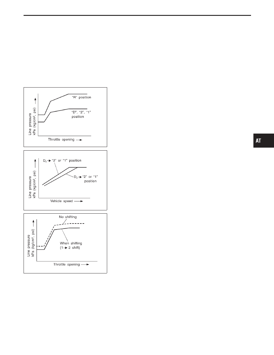
LINE PRESSURE CONTROL
TCM has the various line pressure control characteristics to meet
the driving conditions.
An ON-OFF duty signal is sent to the line pressure solenoid valve
based on TCM characteristics.
Hydraulic pressure on the clutch and brake is electronically con-
trolled through the line pressure solenoid valve to accommodate
engine torque. This results in smooth shift operation.
SAT003J
Normal control
The line pressure to throttle opening characteristics is set for suit-
able clutch operation.
SAT004J
Back-up control (Engine brake)
If the selector lever is shifted to “2” position while driving in D
4
(OD)
or D
3
, great driving force is applied to the clutch inside the trans-
mission. Clutch operating pressure (line pressure) must be
increased to deal with this driving force.
SAT005J
During shift change
The line pressure is temporarily reduced corresponding to a
change in engine torque when shifting gears (that is, when the shift
solenoid valve is switched for clutch operation) to reduce shifting
shock.
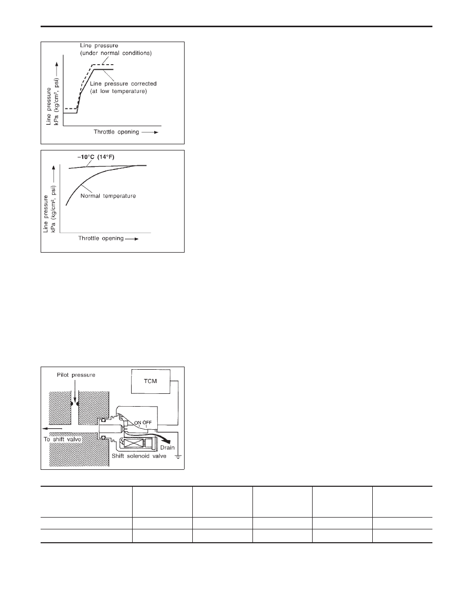
At low fluid temperature
I
Fluid viscosity and frictional characteristics of the clutch facing
change with fluid temperature. Clutch engaging or band-con-
tacting pressure is compensated for, according to fluid
temperature, to stabilize shifting quality.
GI
MA
EM
LC
EC
FE
PD
FA
RA
BR
ST
RS
BT
HA
EL
IDX
OVERALL SYSTEM
AT-31
SAT006J
I
The line pressure is reduced below 60°C (140°F) to prevent
shifting shock due to low viscosity of automatic transmission
fluid when temperature is low.
SAT007J
I
Line pressure is increased to a maximum irrespective of the
throttle opening when fluid temperature drops to −10°C (14°F).
This pressure rise is adopted to prevent a delay in clutch and
brake operation due to extreme drop of fluid viscosity at low
temperature.
SHIFT CONTROL
The shift is regulated entirely by electronic control to accommodate
vehicle speed and varying engine operations. This is accomplished
by electrical signals transmitted by the revolution sensor and
throttle position sensor. This results in improved acceleration per-
formance and fuel economy.
SAT008J
Control of shift solenoid valves A and B
The TCM activates shift solenoid valves A and B according to sig-
nals from the throttle position sensor and revolution sensor to
select the optimum gear position on the basis of the shift schedule
memorized in the TCM.
The shift solenoid valve performs simple ON-OFF operation. When
set to “ON”, the drain circuit closes and pilot pressure is applied to
the shift valve.
Relation between shift solenoid valves A and B and gear positions
Gear position
Shift solenoid valve
D
1
, 2
1
, 1
1
D
2
, 2
2
, 1
2
D
3
D
4
(OD)
N-P
A
ON (Closed)
OFF (Open)
OFF (Open)
ON (Closed)
ON (Closed)
B
ON (Closed)
ON (Closed)
OFF (Open)
OFF (Open)
ON (Closed)
OVERALL SYSTEM
Control Mechanism (Cont’d)
AT-32
Нет комментариевНе стесняйтесь поделиться с нами вашим ценным мнением.
Текст