Infiniti Q45 (FY33). Manual — part 520

Coil Spring and Shock Absorber
NOTE:
For removal and installation procedures of active damper sus-
pension-related parts, refer to “Removal and Installation”,
“ACTIVE DAMPER SUSPENSION” in FA section.
REMOVAL
Remove shock absorber upper and lower fixing nuts.
Do not remove piston rod lock nut on vehicle.
SRA521A
DISASSEMBLY
I
Put matchmarks on coil spring and shock absorber.
SRA806A
1.
Set shock absorber in vise with attachment, then loosen pis-
ton rod lock nut.
WARNING:
Do not remove piston rod lock nut at this time.
2.
Compress spring with tool so that the shock absorber upper
spring seat can be turned by hand.
WARNING:
Make sure that the pawls of the two spring compressors are
firmly hooked on the spring. The spring compressors must be
tightened alternately so as not to tilt the spring.
3.
Remove piston rod lock nut.
INSPECTION
Shock absorber assembly
I
Check for smooth operation through a full stroke, both com-
pression and extension.
I
Check for oil leakage occurring on welded or gland packing
portions.
I
Check piston rod for cracks, deformation or other damage.
Replace if necessary.
Upper rubber seat and bushing
Check rubber parts for deterioration or cracks.
Replace if necessary.
Coil spring
Check for cracks, deformation or other damage. Replace if neces-
sary.
GI
MA
EM
LC
EC
FE
AT
PD
FA
BR
ST
RS
BT
HA
EL
IDX
REAR SUSPENSION
RA-21
SFA664A
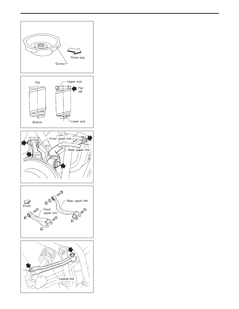
ASSEMBLY
I
Install upper spring seat with its cutout facing the outer side of
vehicle.
SFA436B
I
When installing coil springs, be careful not to reverse top and
bottom direction. (Top end is flat.)
I
When installing coil spring on shock absorber, it must be posi-
tioned as shown in figure at left.
SRA523A
Multi-link and Lower Ball Joint
REMOVAL AND INSTALLATION
I
Remove upper link.
SRA524A
I
Install upper link.
SRA654A
I
Remove lateral link.
REAR SUSPENSION
Coil Spring and Shock Absorber (Cont’d)
RA-22
SRA526A
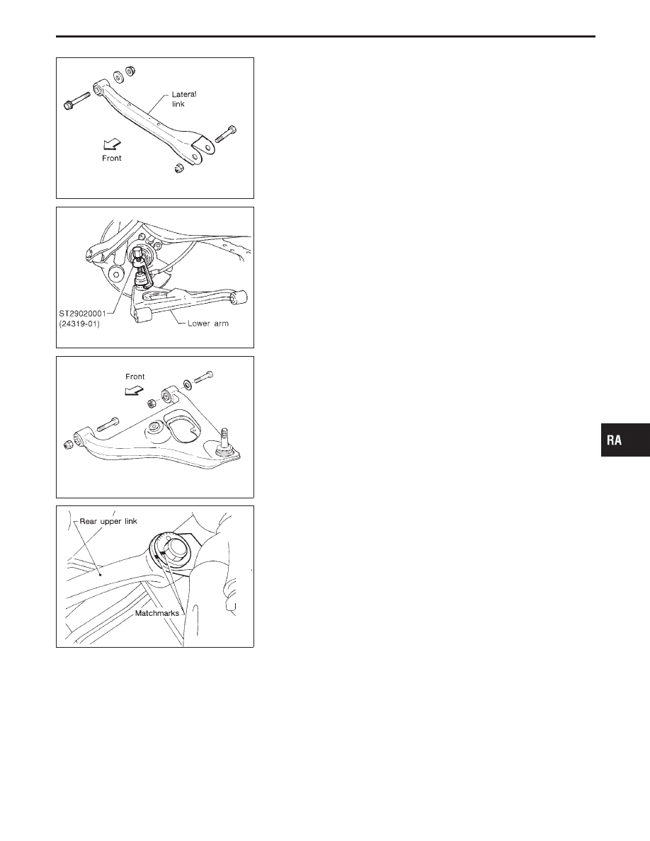
I
Install lateral link.
SRA783A
I
Remove lower arm with Tool.
SRA527A
I
Install lower arm.
SRA660A
Before removing, put matchmarks on adjusting bolt.
I
When installing, final tightening must be done under unladen
condition with tires on ground.
GI
MA
EM
LC
EC
FE
AT
PD
FA
BR
ST
RS
BT
HA
EL
IDX
REAR SUSPENSION
Multi-link and Lower Ball Joint (Cont’d)
RA-23

SRA716A
I
After installation, check wheel alignment. Refer to Rear Wheel
Alignment in ON-VEHICLE SERVICE (RA-7).
INSPECTION
Rear suspension member
Replace suspension member assembly if cracked or deformed or
if any part (insulator, for example) is damaged.
Upper, lower and lateral links
Replace upper, lower or lateral link as required if cracked or
deformed or if bushing is damaged.
SRA131A
Suspension lower ball joint
I
Measure swing force, turning torque and vertical end play in
axial direction. (Use same measurement procedures as that of
FA section.)
I
If ball stud is worn, play in axial direction is excessive, or joint
is hard to swing, replace lower arm.
Ball joint
specifications
Swing force
7.8 - 78.5 N
(0.8 - 8.0 kg, 1.8 - 17.6 lb)
Turning torque
0.5 - 4.9 N
⋅
m
(5 - 50 kg-cm, 4.3 - 43.4 in-lb)
Vertical end play
0 mm (0 in)
REAR SUSPENSION
Multi-link and Lower Ball Joint (Cont’d)
RA-24
Нет комментариевНе стесняйтесь поделиться с нами вашим ценным мнением.
Текст