Infiniti Q45 (FY33). Manual — part 370
SEL962U
DIAGNOSTIC PROCEDURE 8
[Lifting sensor (rear) check]
SEL963U
SEL964U
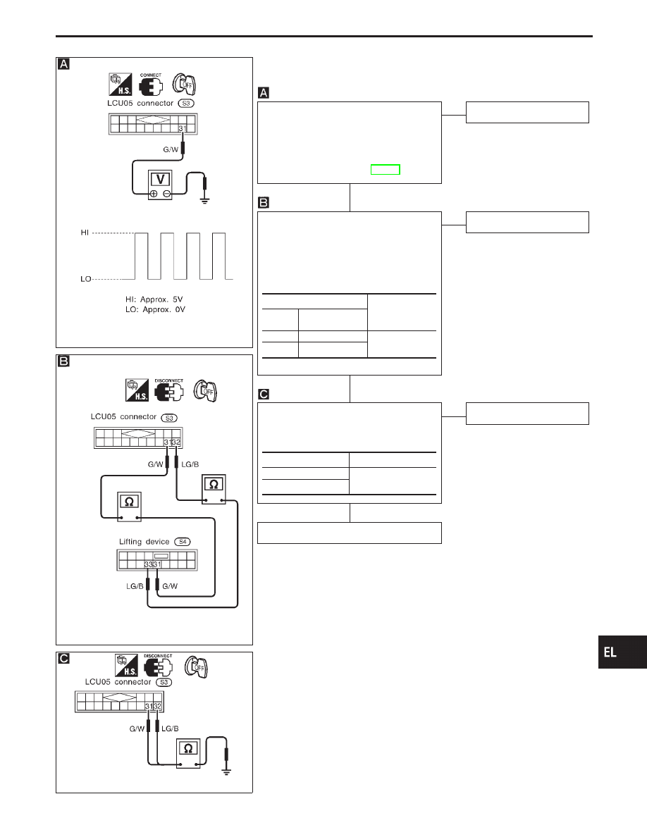
CHECK LIFTING SENSOR (REAR)
INPUT SIGNAL.
Measure voltage between LCU05 terminal
q
31
and ground with oscilloscope when
power seat lifting (rear) is operated.
Refer to wiring diagram in EL-453.
NG
E
OK
Lifting sensor (rear) is OK.
CHECK LIFTING SENSOR (REAR)
OPEN CIRCUIT.
1. Disconnect LCU05 connector and lifting
device connector.
2. Check harness continuity between
LCU05 connector and lifting device con-
nector.
OK
E
NG
Repair harness.
CHECK LIFTING SENSOR (REAR)
SHORT CIRCUIT.
Check harness continuity between LCU05
connector and ground.
OK
E
NG
Repair harness.
Replace lifting sensor (rear).
Terminals
Continuity
LCU05
Lifting device
(Sliding sensor)
q
31
q
31
Yes
q
32
q
33
Terminals
Continuity
q
31
- Ground
No
q
32
- Ground
GI
MA
EM
LC
EC
FE
AT
PD
FA
RA
BR
ST
RS
BT
HA
IDX
AUTOMATIC DRIVE POSITIONER — IVMS
Trouble Diagnoses (Cont’d)
H
H
H
EL-471
SEL545W
DIAGNOSTIC PROCEDURE 9
(Tilt motor check)
SEL966U
SEL967U
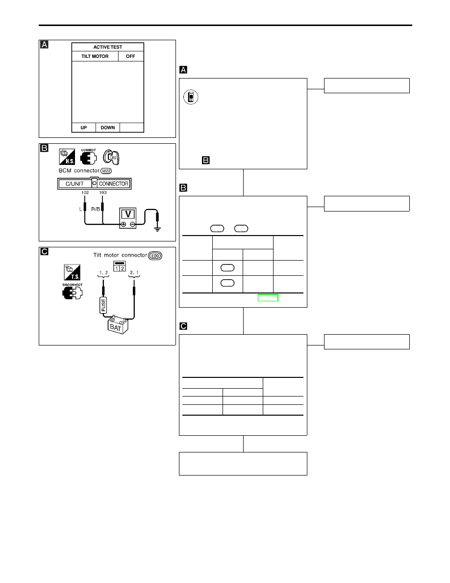
TILT MOTOR ACTIVE TEST
CONSULT-II
See “TILT MOTOR” in ACTIVE TEST
mode.
Perform operation shown on display.
Tilt motor should operate.
Note: If CONSULT-II is not available,
start with diagnostic procedure
.
NG
E
OK
Tilt motor is OK.
CHECK OUTPUT SIGNAL TO TILT
MOTOR.
Check voltage between BCM connector
terminals
102
or
103
and ground.
Refer to wiring diagram in EL-450.
OK
E
NG
Replace BCM.
CHECK TILT MOTOR.
1. Disconnect tilt motor connector.
2. Apply 12V DC direct current to motor
and check operation.
OK
E
NG
Replace tilt motor.
Check harness for operation between
BCM and tilt motor.
Condition
of tilt
switch
Terminals
Voltage
V
!
@
Up
103
Ground
Approx.
12
Down
102
Ground
Approx.
12
Terminals
Operation
!
@
q
1
q
2
Up
q
2
q
1
Down
AUTOMATIC DRIVE POSITIONER — IVMS
Trouble Diagnoses (Cont’d)
H
H
H
EL-472
SEL546W
DIAGNOSTIC PROCEDURE 10
(Telescopic motor check)
SEL969U
SEL970U
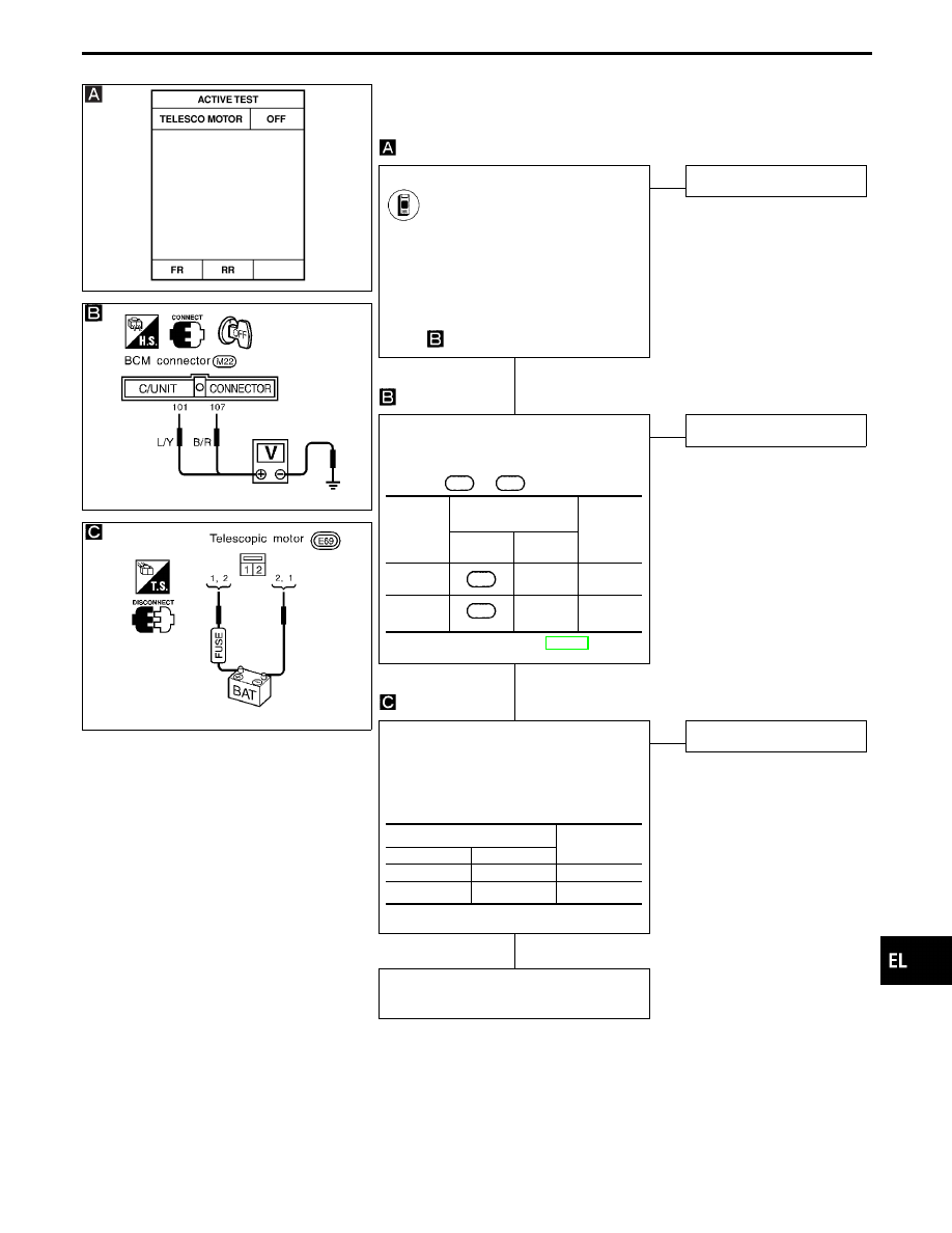
TELESCOPIC MOTOR ACTIVE TEST
CONSULT-II
See “TELESCO MOTOR” in ACTIVE
TEST mode.
Perform operation shown on display.
Telescopic motor should operate.
Note: If CONSULT-II is not available,
start with diagnostic procedure
.
NG
E
OK
Telescopic motor is OK.
CHECK OUTPUT SIGNAL TO TELE-
SCOPIC MOTOR.
Check voltage between BCM connector
terminals
101
or
107
and ground.
Refer to wiring diagram in EL-450.
OK
E
NG
Replace BCM.
CHECK TELESCOPIC MOTOR.
1. Disconnect telescopic motor connector.
2. Apply 12V DC direct current to motor
and check operation.
OK
E
NG
Replace telescopic motor.
Check harness for operation between
BCM and telescopic motor.
Condition
of tele-
scopic
switch
Terminals
Voltage
V
!
@
Forward
101
Ground
Approx.
12
Backward
107
Ground
Approx.
12
Terminals
Operation
!
@
q
1
q
2
Forward
q
2
q
1
Upward
GI
MA
EM
LC
EC
FE
AT
PD
FA
RA
BR
ST
RS
BT
HA
IDX
AUTOMATIC DRIVE POSITIONER — IVMS
Trouble Diagnoses (Cont’d)
H
H
H
EL-473
SEL547W
DIAGNOSTIC PROCEDURE 11
(Sliding motor check)
SEL972U
SEL973U
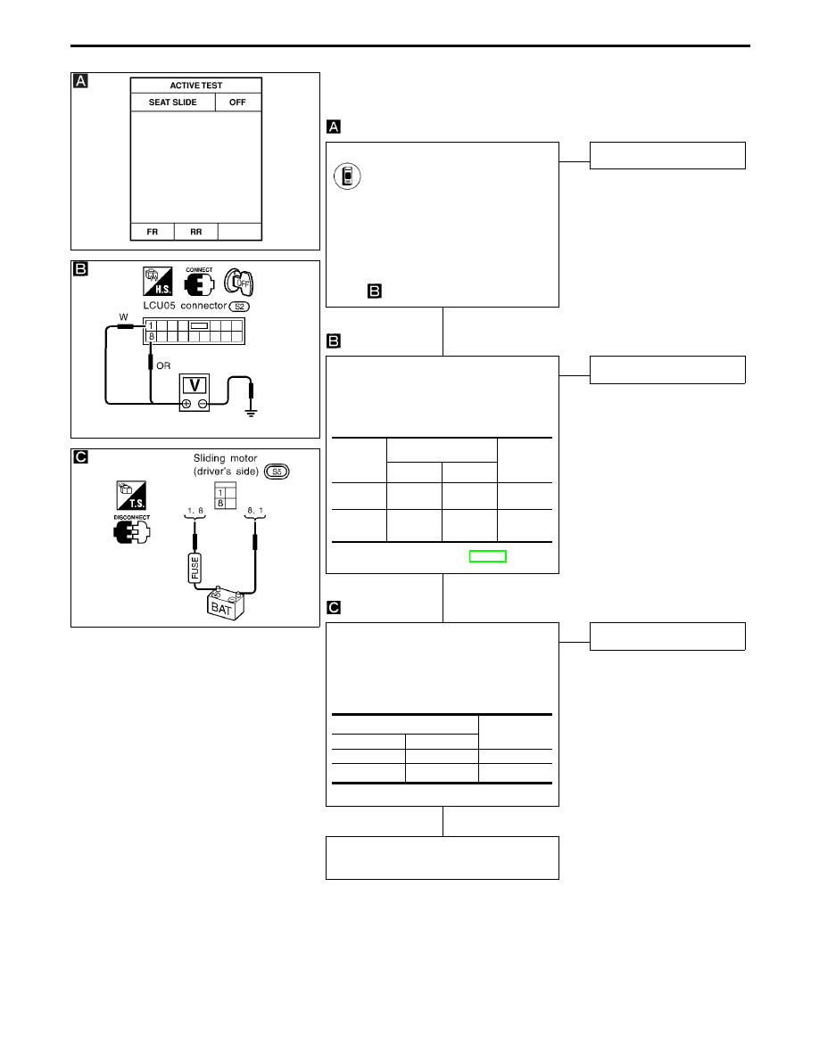
SLIDING SLIDE ACTIVE TEST
CONSULT-II
See “SEAT SLIDE” in ACTIVE TEST
mode.
Perform operation shown on display.
Sliding motor should operate.
Note: If CONSULT-II is not available,
start with diagnostic procedure
.
NG
E
OK
Sliding motor is OK.
CHECK OUTPUT SIGNAL TO SLIDING
MOTOR.
Check voltage between LCU05 connector
terminals
q
1
or
q
8
and ground.
Refer to wiring diagram in EL-452.
OK
E
NG
Replace LCU05.
CHECK SLIDING MOTOR.
1. Disconnect sliding motor connector.
2. Apply 12V DC direct current to motor
and check operation.
OK
E
NG
Replace sliding motor.
Check harness for operation between
LCU05 and sliding motor.
Condition
of sliding
switch
Terminals
Voltage
V
!
@
Forward
q
1
Ground
Approx.
12
Backward
q
8
Ground
Approx.
12
Terminals
Operation
!
@
q
1
q
8
Forward
q
8
q
1
Backward
AUTOMATIC DRIVE POSITIONER — IVMS
Trouble Diagnoses (Cont’d)
H
H
H
EL-474
Нет комментариевНе стесняйтесь поделиться с нами вашим ценным мнением.
Текст