Infiniti Q45 (FY33). Manual — part 77

SBR019B
RUNOUT
1.
Secure rotor to wheel hub with two nuts (M12 x 1.25).
2.
Check runout using a dial indicator.
Make sure that wheel bearing axial end play is within the
specifications before measuring. Refer to RA section, “Rear
Wheel Bearing”.
Maximum runout:
0.07 mm (0.0028 in)
3.
If the runout is out of specification, find minimum runout posi-
tion as follows:
a. Remove nuts and rotor from wheel hub.
b. Shift the rotor one hole and secure rotor to wheel hub with
nuts.
c. Measure runout.
d. Repeat steps a. to c. so that minimum runout position can
be found.
4.
If the runout is still out of specification, turn rotor with on-car
brake lathe (“MAD, DL-8700”, “AMMCO 700 and 705” or
equivalent).
SBR020B
THICKNESS
Rotor repair limit:
Minimum thickness
14.0 mm (0.551 in)
Thickness variation (At least 8 portions)
Maximum 0.02 mm (0.0008 in)
If thickness variation exceeds the specification, turn rotor with on-
car brake lathe.
SBR044C
Assembly
1.
Insert piston seal into groove on cylinder body.
2.
With piston boot fitted to piston, insert piston boot into groove
on cylinder body and install piston.
3.
Properly secure piston boot.
4.
Secure piston boot with retainer.
SBR093C
Installation
CAUTION:
I
Refill with new brake fluid “DOT 3”.
I
Never reuse drained brake fluid.
1.
Install caliper assembly.
Do not forget to install shims and washers.
2.
Install brake hose to caliper securely.
3.
Install all parts and secure all bolts.
4.
Bleed air. Refer to “Bleeding Brake System”, BR-7.
GI
MA
EM
LC
EC
FE
AT
PD
FA
RA
ST
RS
BT
HA
EL
IDX
REAR DISC BRAKE
Inspection — Rotor (Cont’d)
BR-25

JBR300D
q
1
Parking brake cable
q
2
Back plate
q
3
Anchor block
q
4
E-ring
q
5
Lever
q
6
Pin
q
7
Toggle lever
q
8
Stopper pin
q
9
Return spring
q
10
Shoe
q
11
Adjuster spring
q
12
Anti-rattle spring
q
13
Retainer
q
14
Anti-rattle pin
q
15
Adjuster assembly LH
q
16
Adjuster assembly RH
SBR094C
Removal
WARNING:
Clean brakes with a vacuum dust collector to minimize the
hazard of airborne particles or other materials.
CAUTION:
Make sure parking brake lever is released completely.
1.
Remove torque member fixing bolts (Rear disc brake assem-
bly mounting bolts).
Suspend caliper assembly with wire so as not to stretch brake
hose.
REAR DISC BRAKE — Parking Drum Brake
BR-26

SBR046CA
2.
Release parking brake lever fully, then remove drum.
If drum is hard to remove, the following procedures should be
carried out.
a.
Remove plug.
b.
Insert flat-bladed screwdriver through plug hole.
c.
Turn adjuster to make clearance between brake shoe and
drum.
SBR764A
d.
Fit two bolts to the drum as shown and tighten gradually.
SBR765A
3.
After removing retainer, remove spring by rotating shoes.
4.
Remove adjuster.
SBR095C
5.
Disconnect parking brake cable from toggle lever after draw-
ing out toggle lever pin.
SBR768A
Inspection — Drum
Maximum inner diameter:
173.0 mm (6.81 in)
GI
MA
EM
LC
EC
FE
AT
PD
FA
RA
ST
RS
BT
HA
EL
IDX
REAR DISC BRAKE — Parking Drum Brake
Removal (Cont’d)
BR-27
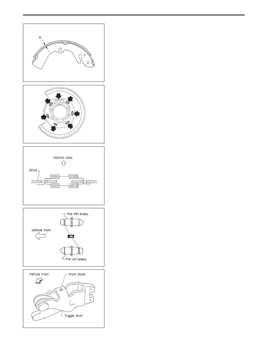
SBR021A
Inspection — Lining
Check lining thickness.
Standard lining thickness:
3.2 mm (0.126 in)
Lining wear limit (A):
1.5 mm (0.059 in)
SBR047C
Installation
1.
Apply brake grease to the contact areas shown at left.
SBR301D
2.
Attach two upper springs to brake shoes as shown in the fig-
ure at left.
SBR949A
3.
Shorten adjuster by rotating it.
Pay attention to direction of adjuster.
SBR096C
4.
Connect parking brake cable to toggle lever.
Pay attention to direction of adjuster.
5.
Install all parts.
REAR DISC BRAKE — Parking Drum Brake
BR-28
Нет комментариевНе стесняйтесь поделиться с нами вашим ценным мнением.
Текст