Infiniti Q45 (FY33). Manual — part 184
SEF575Q
SEF156I
SEF112T
q
A
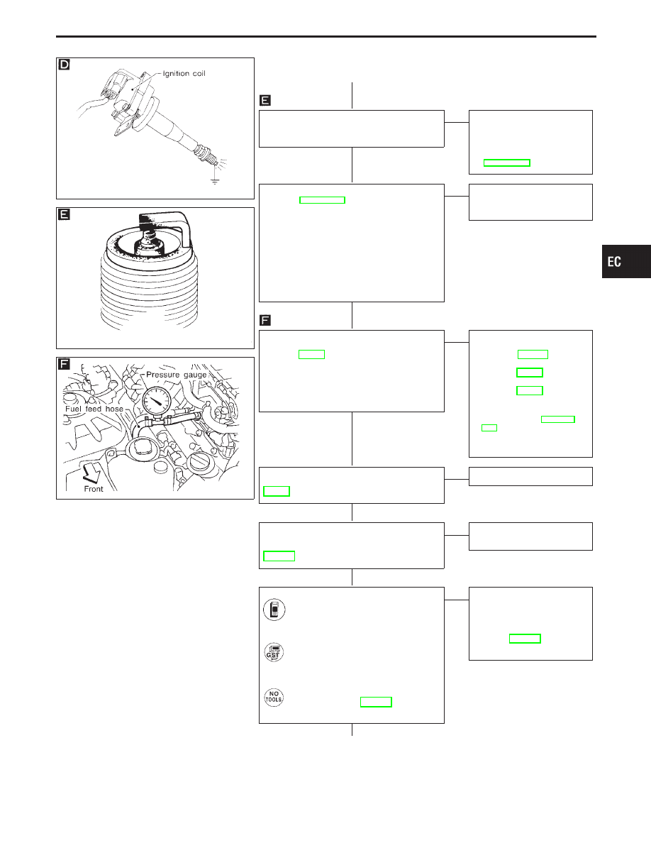
CHECK SPARK PLUGS.
Remove the spark plugs and check for
fouling, etc.
OK
E
NG
Repair or replace spark
plug(s) with standard type
one(s).
For spark plug type, refer to
“ENGINE MAINTENANCE”
in MA section.
CHECK COMPRESSION PRESSURE.
Refer to EM section.
I
Check compression pressure.
Standard:
kPa (kg/cm
2
, psi)/300 rpm
1,285 (13.1, 186)
Minimum:
kPa (kg/cm
2
, psi)/300 rpm
991 (10.1, 144)
Difference between each cylinder:
kPa (kg/cm
2
, psi)/300 rpm
98 (1.0, 14)
OK
E
NG
Check pistons, piston rings,
valves, valve seats and cyl-
inder head gaskets.
CHECK FUEL PRESSURE.
1. Release fuel pressure to zero. Refer to
page EC-37.
2. Install fuel pressure gauge and check
fuel pressure.
At idle:
Approx. 235 kPa
(2.4 kg/cm
2
, 34 psi)
OK
E
NG
Check the following.
I
Fuel pump and circuit
Refer to EC-523.
I
Fuel pressure regulator
Refer to EC-37.
I
Fuel lines
Refer to EC-38.
I
Fuel lines
Refer to “ENGINE MAIN-
TENANCE” in MA sec-
tion.
I
Fuel filter for clogging
If NG, repair or replace.
CHECK IGNITION TIMING.
Perform “BASIC INSPECTION”,
EC-91.
OK
E
NG
Adjust ignition timing.
CHECK COMPONENT
[Heated oxygen sensor 1 (front)].
Refer to “COMPONENT INSPECTION”,
EC-172.
OK
E
NG
Replace heated oxygen
sensor 1 (front).
CHECK MASS AIR FLOW SENSOR.
Check “MASS AIR FLOW” in “DATA
MONITOR” mode with CONSULT-II.
3.0 - 6.0 g
⋅
m/sec: at idling
12.9 - 25.3 g
⋅
m/sec: at 2,500 rpm
-------------------------------------------------------------------------------------------------------------------------------------- OR --------------------------------------------------------------------------------------------------------------------------------------
Check “mass air flow” in MODE 1
with GST.
3.0 - 6.0 g
⋅
m/sec: at idling
12.9 - 25.3 g
⋅
m/sec: at 2,500 rpm
-------------------------------------------------------------------------------------------------------------------------------------- OR --------------------------------------------------------------------------------------------------------------------------------------
Check mass air flow sensor output
voltage, refer to EC-131.
Approximately 2.1V: at 2,500 rpm
OK
E
NG
Check connectors for
rusted terminals or loose
connections in the mass air
flow sensor circuit or engine
grounds.
Refer to EC-124.
If NG, repair or replace it.
(Go to
q
B
on next page.)
GI
MA
EM
LC
FE
AT
PD
FA
RA
BR
ST
RS
BT
HA
EL
IDX
TROUBLE DIAGNOSIS FOR DTC P0300 - P0308
No. 1 - 8 Cylinder Misfire, Multiple Cylinder
Misfire (Cont’d)
H
H
H
H
H
H
H
EC-265

q
B
CHECK SYMPTOM MATRIX CHART.
Check items on the rough idle symptom in
“Symptom Matrix Chart”, EC-99.
OK
E
NG
Repair or replace.
Some tests may cause a Diagnostic
Trouble Code to be set.
Erase the DTC from the ECM memory
after performing the tests. Refer to EC-67.
Perform “TROUBLE DIAGNOSIS FOR
INTERMITTENT INCIDENT”, EC-117.
INSPECTION END
TROUBLE DIAGNOSIS FOR DTC P0300 - P0308
No. 1 - 8 Cylinder Misfire, Multiple Cylinder
Misfire (Cont’d)
H
H
H
H
EC-266
SEF598K
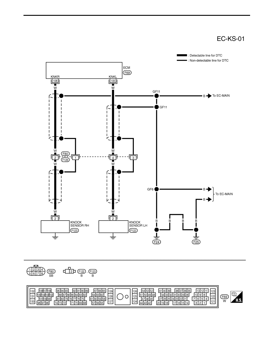
Knock Sensor (KS) (P0325: Left bank), (P0330:
Right bank)
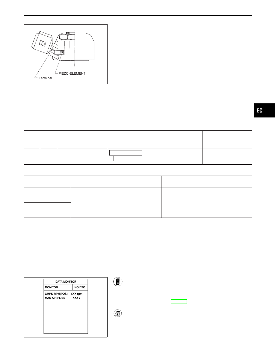
COMPONENT DESCRIPTION
The knock sensor is attached to the cylinder block. It senses
engine knocking using a piezoelectric element. A knocking vibration
from the cylinder block is sensed as vibrational pressure. This
pressure is converted into a voltage signal and sent to the ECM.
* Freeze frame data is not stored in the ECM for the knock sensor. The MIL will not light for knock
sensor malfunction.
ECM TERMINALS AND REFERENCE VALUE
Specification data are reference values, and are measured between each terminal and ground.
CAUTION:
Do not use ECM ground terminals when measuring voltage. Doing so may result in damage to the
ECM’s transistor. Use a ground other than ECM terminals such as the body ground.
TER-
MINAL
NO.
WIRE
COLOR
ITEM
CONDITION
DATA
(DC voltage)
105
108
W
W
Knock sensor (RH)
Knock sensor (LH)
Engine is running.
Idle speed
2.0 - 3.0V
ON BOARD DIAGNOSIS LOGIC
Diagnostic Trouble Code
No.
Malfunction is detected when .
Check Items
(Possible Cause)
P0325
0304
(Bank 1)
I
An excessively low or high voltage from the
knock sensor is sent to ECM.
I
Harness or connectors
(The knock sensor circuit is open or shorted.)
I
Knock sensor
P0330
0212
(Bank 2)
DIAGNOSTIC TROUBLE CODE CONFIRMATION
PROCEDURE
NOTE:
Before performing the following procedure, confirm that bat-
tery voltage is more than 10V.
SEF400X
1) Turn ignition switch “ON” and select “DATA MONITOR”
mode with CONSULT-II.
2) Start engine and run it for at least 5 seconds at idle
speed.
3) If 1st trip DTC is detected, go to “DIAGNOSTIC
PROCEDURE”, EC-269.
------------------------------------------------------------------------------------------------------------------------------------------------------------------------------------------------------------------------------------------------------ OR ------------------------------------------------------------------------------------------------------------------------------------------------------------------------------------------------------------------------------------------------------
Follow the procedure “With CONSULT-II” above.
GI
MA
EM
LC
FE
AT
PD
FA
RA
BR
ST
RS
BT
HA
EL
IDX
TROUBLE DIAGNOSIS FOR DTC P0325 (B1), P0330 (B2)
EC-267
TEC086M
TROUBLE DIAGNOSIS FOR DTC P0325 (B1), P0330 (B2)
Knock Sensor (KS) (P0325: Left bank), (P0330:
Right bank) (Cont’d)
EC-268
Нет комментариевНе стесняйтесь поделиться с нами вашим ценным мнением.
Текст