Infiniti Q45 (FY33). Manual — part 217
SEF153T
SEF426Q
SEF438U
q
A
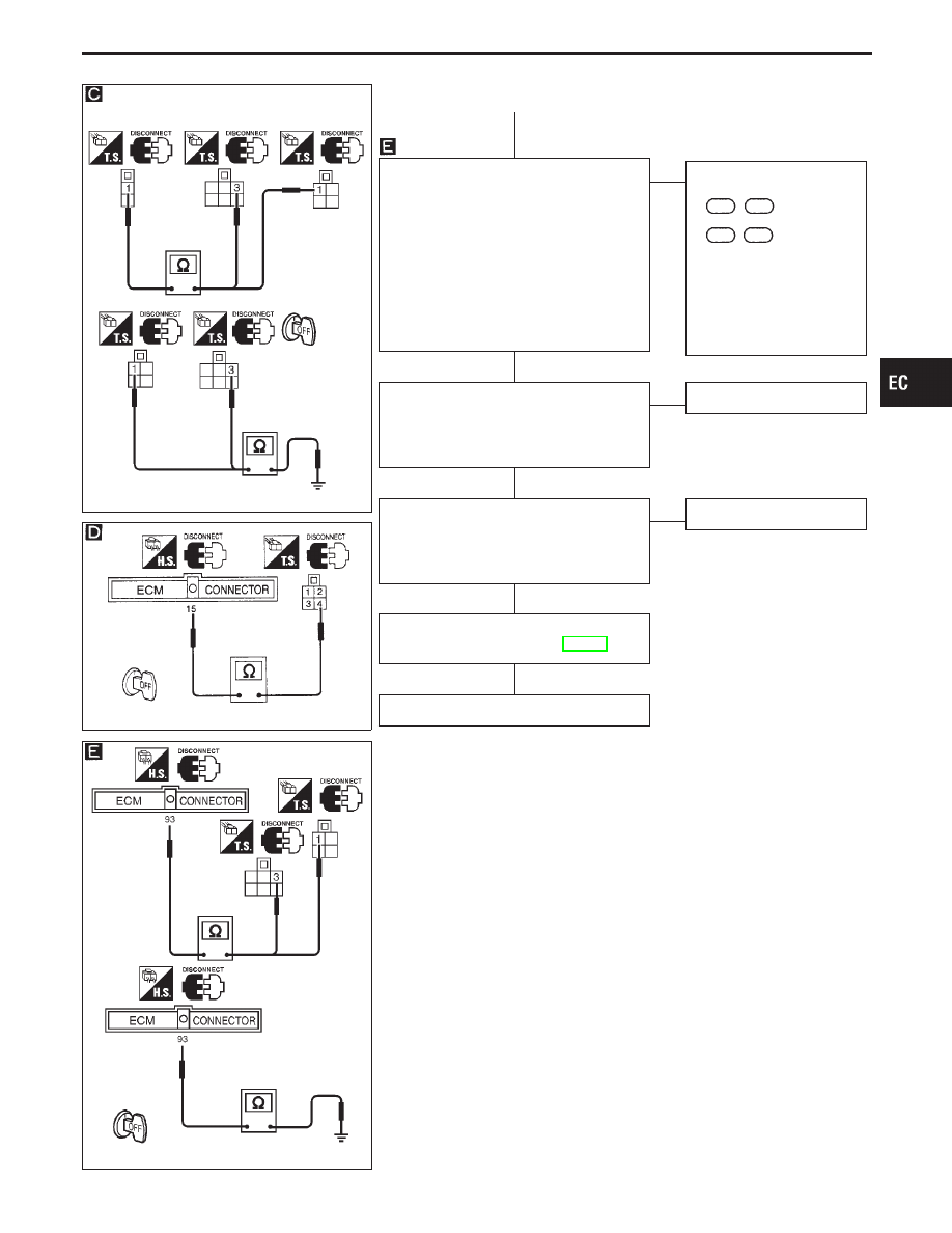
CHECK INPUT SIGNAL CIRCUIT.
1. Check harness continuity between ECM
terminal
q
93
and terminal
q
1
(or fuel
pump terminal
q
3
).
Continuity should exist.
2. Check harness continuity between ECM
terminal
q
93
and engine ground.
Continuity should not exist.
If OK, check harness for short to
ground and short to power.
OK
E
NG
Check the following.
I
Harness connectors
F63
,
M49
I
Harness connectors
M4
,
B3
I
Harness for open or
short between ECM and
FPCM (or fuel pump)
If NG, repair open circuit or
short to ground or short to
power in harness or con-
nectors.
CHECK COMPONENT
(Dropping resistor).
Refer to “COMPONENT INSPECTION” on
next page.
OK
E
NG
Replace dropping resistor.
CHECK COMPONENT
(FPCM).
Refer to “COMPONENT INSPECTION” on
next page.
OK
E
NG
Replace FPCM.
Perform “TROUBLE DIAGNOSIS FOR
INTERMITTENT INCIDENT”, EC-117.
INSPECTION END
GI
MA
EM
LC
FE
AT
PD
FA
RA
BR
ST
RS
BT
HA
EL
IDX
TROUBLE DIAGNOSIS FOR DTC P1220
Fuel Pump Control Module (FPCM) (Cont’d)
H
H
H
H
H
EC-397
SEF770X
SEF771X
SEF525Y
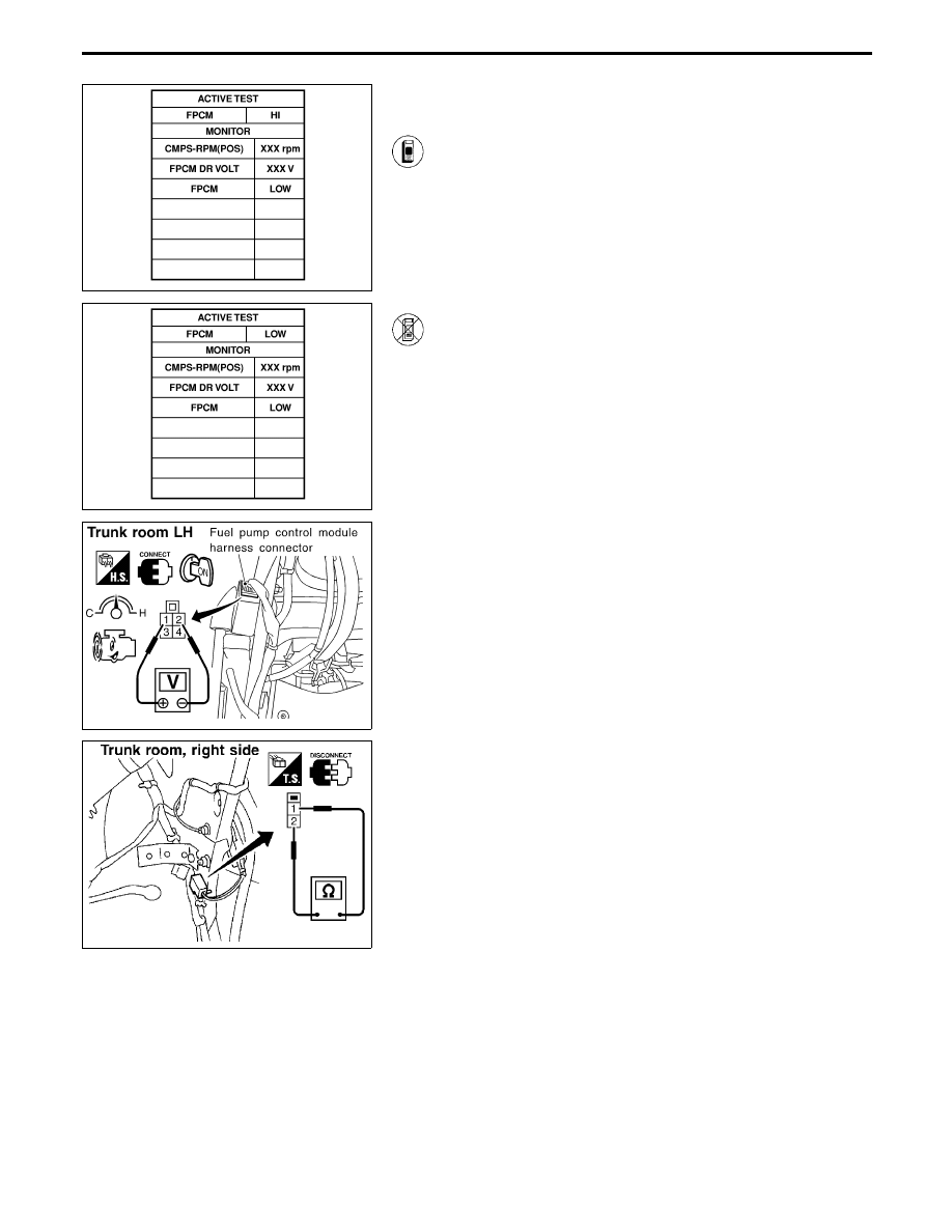
COMPONENT INSPECTION
FPCM
1. Start engine and let it idle.
2. Perform “FPCM” in “ACTIVE TEST” mode with CON-
SULT-II.
3. Check the following.
I
When selecting “HI”, “FPCM DR VOLT” indicates
approximately 0V.
I
When selecting “LOW”, “FPCM DR VOLT” indicates
approximately 4.4V.
4. If NG, replace FPCM.
------------------------------------------------------------------------------------------------------------------------------------------------------------------------------------------------------------------------------------------------------ OR ------------------------------------------------------------------------------------------------------------------------------------------------------------------------------------------------------------------------------------------------------
1. Start engine and warm it up to normal operating tempera-
ture.
2. Turn ignition switch “OFF” and wait at least 5 seconds.
3. Start engine and let it idle.
4. Check voltage between terminals
q
1
and
q
2
.
Within 30 seconds of starting engine:
Approximately 0V
More than 30 seconds after starting engine:
Approximately 4.4V
5. If NG, replace FPCM.
SEF156T
Dropping resistor
Check resistance between terminals
q
1
and
q
2
.
Resistance: Approximately 0.8
Ω
at 25°C (77°F)
TROUBLE DIAGNOSIS FOR DTC P1220
Fuel Pump Control Module (FPCM) (Cont’d)
EC-398
SEF304T
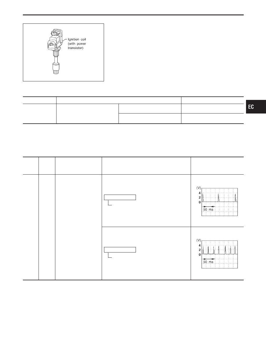
Ignition Signal
COMPONENT DESCRIPTION
Ignition coil & power transistor
The ignition signal from the ECM is sent to and amplified by the
power transistor. The power transistor turns on and off the ignition
coil primary circuit. This on-off operation induces the proper high
voltage in the coil secondary circuit.
CONSULT-II REFERENCE VALUE IN DATA MONITOR MODE
Specification data are reference values.
MONITOR ITEM
CONDITION
SPECIFICATION
IGN TIMING
I
Engine: After warming up
I
Air conditioner switch: “OFF”
I
Shift lever: “N”
I
No-load
Idle
15° BTDC
2,000 rpm
More than 25° BTDC
ECM TERMINALS AND REFERENCE VALUE
Specification data are reference values, and are measured between each terminal and ground.
CAUTION:
Do not use ECM ground terminals when measuring voltage. Doing so may result in damage to the
ECM’s transistor. Use a ground other than ECM terminals such as the body ground.
TER-
MINAL
NO.
WIRE
COLOR
ITEM
CONDITION
DATA
(DC voltage)
43
44
46
47
50
51
53
54
Y/R
G/R
L/R
GY
PU/W
GY/R
W/R
R/L
Ignition signal (No. 1)
Ignition signal (No. 8)
Ignition signal (No. 7)
Ignition signal (No. 3)
Ignition signal (No. 6)
Ignition signal (No. 5)
Ignition signal (No. 4)
Ignition signal (No. 2)
Engine is running. (Warmed-up condition)
Idle speed
Approximately 0.38V
SEF538T
Engine is running. (Warmed-up condition)
Engine speed is 2,000 rpm.
Approximately 0.55V
SEF539T
GI
MA
EM
LC
FE
AT
PD
FA
RA
BR
ST
RS
BT
HA
EL
IDX
TROUBLE DIAGNOSIS FOR DTC P1320
EC-399
ON BOARD DIAGNOSIS LOGIC
Diagnostic Trouble
Code No.
Malfunction is detected when ...
Check Items
(Possible Cause)
P1320
0201
I
The ignition signal in the primary circuit is not sent
during engine cranking or running.
I
Harness or connectors
(The ignition primary circuit is open or shorted.)
I
Power transistor unit built into ignition coil
I
Camshaft position sensor
I
Camshaft position sensor circuit
SEF400X
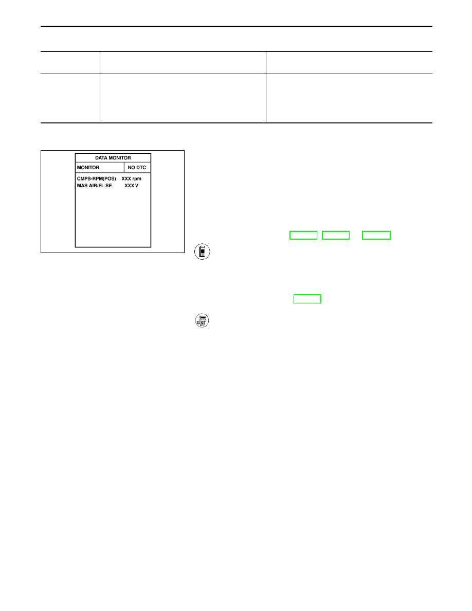
DIAGNOSTIC TROUBLE CODE CONFIRMATION
PROCEDURE
NOTE:
I
If “DIAGNOSTIC TROUBLE CODE CONFIRMATION PRO-
CEDURE” has been previously conducted, always turn
ignition switch “OFF” and wait at least 5 seconds before
conducting the next test.
I
If DTC P1320 is displayed with DTC P0335, P0340 or
P1336, perform trouble diagnosis for DTC P0335, P0340 or
P1336 first. Refer to EC-270, EC-275 or EC-407.
1) Turn ignition switch “ON”.
2) Select “DATA MONITOR” mode with CONSULT-II.
3) Start engine and wait at least 4 seconds. (If engine does
not run, turn ignition switch to “START” for at least 5
seconds.)
4) If 1st trip DTC is detected, go to “DIAGNOSTIC
PROCEDURE”, EC-404.
------------------------------------------------------------------------------------------------------------------------------------------------------------------------------------------------------------------------------------------------------ OR ------------------------------------------------------------------------------------------------------------------------------------------------------------------------------------------------------------------------------------------------------
Follow the procedure “With CONSULT-II” above.
TROUBLE DIAGNOSIS FOR DTC P1320
Ignition Signal (Cont’d)
EC-400
Нет комментариевНе стесняйтесь поделиться с нами вашим ценным мнением.
Текст