Infiniti Q45 (FY33). Manual — part 455
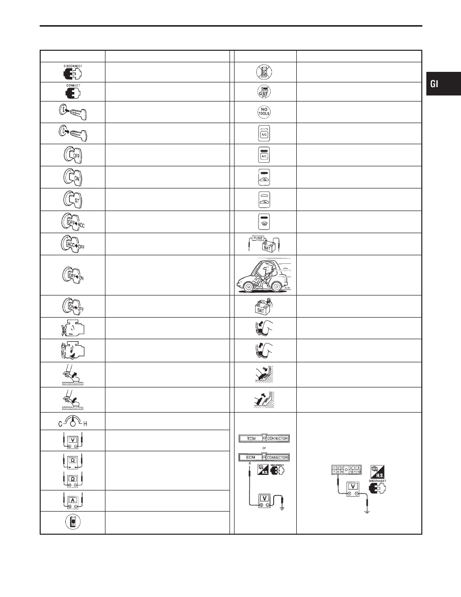
Key to symbols signifying measurements or procedures
Symbol
Symbol explanation
Symbol
Symbol explanation
Check after disconnecting the connector
to be measured.
Procedure without CONSULT-II
Check after connecting the connector to
be measured.
Procedure with Generic Scan Tool (GST,
OBD-II scan tool)
Insert key into ignition switch.
Procedure without CONSULT-II or GST
Remove key from ignition switch.
A/C switch is “OFF”.
Turn ignition switch to “OFF” position.
A/C switch is “ON”.
Turn ignition switch to “ON” position.
REC switch is “ON”.
Turn ignition switch to “START” position.
REC switch is “OFF”.
Turn ignition switch from “OFF” to “ACC”
position.
DEF switch is “ON”.
Turn ignition switch from “ACC” to “OFF”
position.
Apply positive voltage from battery with
fuse directly to components.
Turn ignition switch from “OFF” to “ON”
position.
Drive vehicle.
Turn ignition switch from “ON” to “OFF”
position.
Disconnect battery negative cable.
Do not start engine, or check with engine
stopped.
Depress brake pedal.
Start engine, or check with engine run-
ning.
Release brake pedal.
Apply parking brake.
Depress accelerator pedal.
Release parking brake.
Release accelerator pedal.
Check after engine is warmed up suffi-
ciently.
Pin terminal check for SMJ type ECM
and TCM connectors.
For details regarding the terminal
arrangement, refer to the foldout page.
Voltage should be measured with a volt-
meter.
Circuit resistance should be measured
with an ohmmeter.
Current should be measured with an
ammeter.
Procedure with CONSULT-II
MA
EM
LC
EC
FE
AT
PD
FA
RA
BR
ST
RS
BT
HA
EL
IDX
HOW TO FOLLOW FLOW CHART IN TROUBLE DIAGNOSES
How to Follow This Flow Chart (Cont’d)
GI-35

Function and System Application
Diagnostic
test mode
Function
ENGINE
TCS
A/T
ACT
D/SUS
ABS
AIR
BAG
ASCD IVMS IVCS*1
IVIS
(NATS)*2
Work support
This mode enables a technician
to adjust some devices faster
and more accurate by following
the indications on CONSULT-II.
x
x
x
—
x
—
—
—
—
—
Self-diagnos-
tic results
Self-diagnostic results can be
read and erased quickly.
x
x
x
x
x
x
x
x
x
x
Trouble diag-
nostic record
Current self-diagnostic results
and all trouble diagnostic records
previously stored can be read.
—
—
—
—
—
x
—
—
—
—
ECU dis-
criminated
No.
Classification number of a
replacement ECU can be read to
prevent an incorrect ECU from
being installed.
—
—
—
—
—
x
—
—
—
—
Data monitor
Input/Output data in the ECU
(ECM) can be read.
x
x
x
x
x
—
x
x
x
—
DTC work
support
This mode enables a technician
to set operating conditions to
confirm self-diagnosis status/
results.
—
—
x
—
—
—
—
—
—
—
Active test
Diagnostic Test Mode in which
CONSULT-II drives some actua-
tors apart from the ECUs (ECMs)
and also shifts some parameters
in a specified range.
x
x
—
x
x
—
—
x
—
—
ECU (ECM)
part number
ECU (ECM) part number can be
read.
x
x
x
x
x
—
—
x
x
—
Control unit
initialization
All registered ignition key IDs in
NATS components can be initial-
ized and new IDs can be regis-
tered.
—
—
—
—
—
—
—
—
—
x
Self-function
check
ECM checks its own NATS com-
munication interface.
—
—
—
—
—
—
—
—
—
x
DTC & SRT
confirmation
The results of SRT (System
Readiness Test) and the self-
diagnosis status/results can be
confirmed.
x
—
—
—
—
—
—
—
—
—
Function
check
“Remote door unlock function” of
IVCS system can be checked in
this mode.
—
—
—
—
—
—
—
—
x
—
Registered
data
Display the VIN, etc. data regis-
tered in the IVCS unit.
—
—
—
—
—
—
—
—
x
—
Configuration
I
The IVCS system can be set
up in the demonstration mode
to confirm system operation.
I
Various data related to both
the Communicator Response
Center contract and cellular
provider can be written/
rewritten in this mode.
—
—
—
—
—
—
—
—
x
—
x: Applicable
*1: INFINITI Communicator (IVCS)
*2: IVIS (NATS) [INFINITI Vehicle Immobilizer System (Nissan Anti-Theft System)]
Nickel Metal Hydride Battery Replacement
CONSULT-II contains a nickel metal hydride battery. When replacing the battery obey the following:
WARNING:
Replace the nickel metal hydride battery with Genuine CONSULT-II battery only. Use of another bat-
tery may present a risk of fire or explosion. The battery may present a fire or chemical burn hazard if
mistreated. Do not recharge, disassemble of dispose of in fire.
Keep the battery out of reach of children and discard used battery conforming to the local regulations.
CONSULT-II CHECKING SYSTEM
GI-36
Checking Equipment
When ordering the below equipment, contact your NISSAN/INFINITI distributor.
Tool name
Description
NISSAN CONSULT-II
q
1
CONSULT-II unit and (Tester
internal soft: Resident ver-
sion 3.2.0) accessories
q
2
Program card AED00A (Ver-
sion 4.10) and AEN00A (Ver-
sion 2.0) (For IVIS and
IVCS)
For details, refer to CON-
SULT-II Operation Manual.
SGI100A
NOTE:
I
The CONSULT-II must be used in conjunction with a program card.
CONSULT-II does not require loading (Initialization) procedure.
I
Be sure the CONSULT-II is turned off before installing or removing a program card.
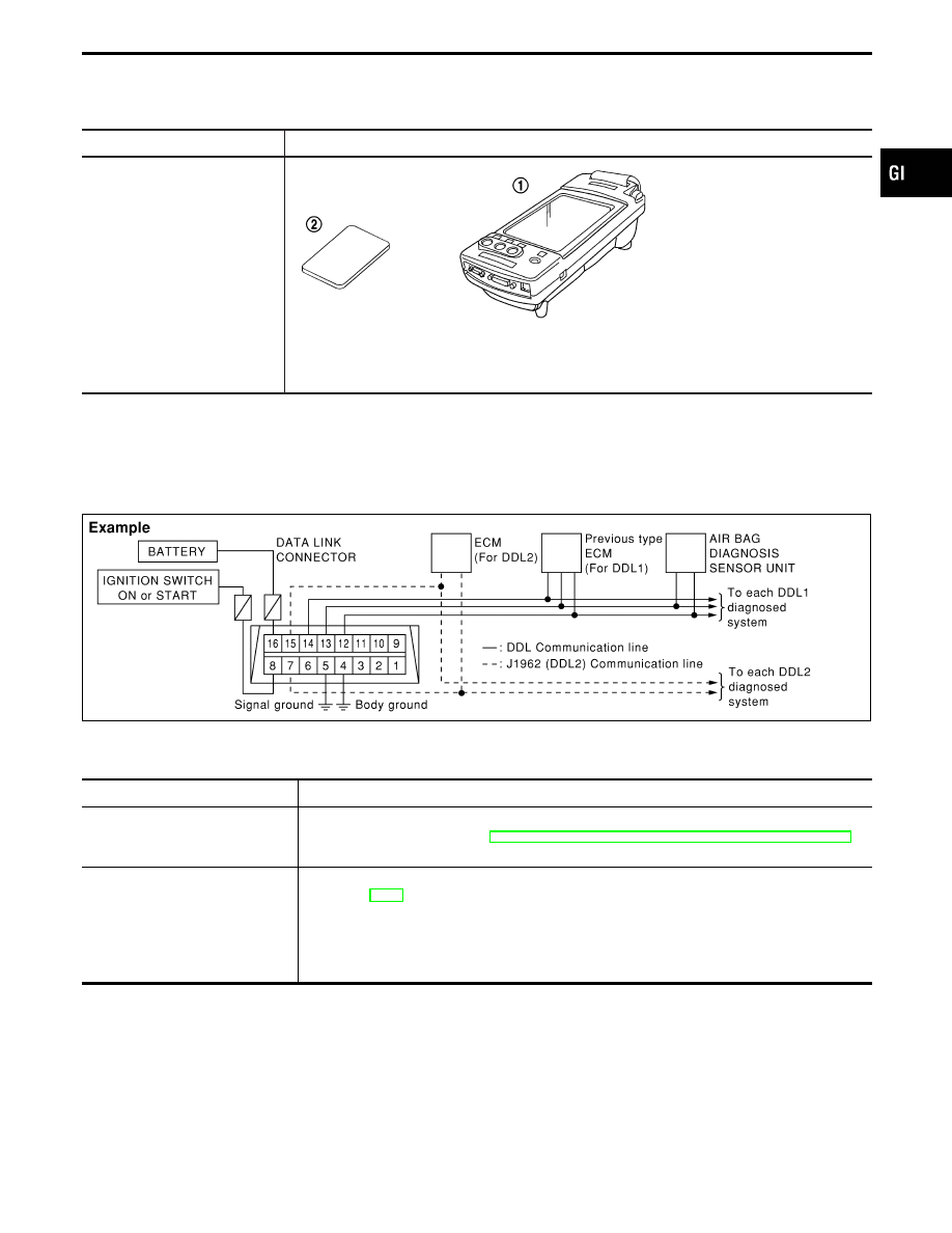
CONSULT-II Data Link Connector (DLC) Circuit
SOM397
INSPECTION PROCEDURE
If the CONSULT-II cannot diagnose the system properly, check the following items.
Symptom
Check item
CONSULT-II cannot access any
system.
I
CONSULT-II DLC power supply circuit (Terminal 8) and ground circuit (Terminal 4)
(For detailed circuit, refer to “MIL & Data Link Connectors Wiring Diagram” in EC section.)
I
CONSULT-II DDL cable
CONSULT-II cannot access indi-
vidual system. (Other systems can
be accessed.)
Refer to “Function and System
Application” for the systems sup-
ported by CONSULT-II.
I
CONSULT-II program card (Check the approprite CONSULT-II program card for the system.
Refer to GI-37.)
I
Power supply and ground circuit for the control unit of the system
(For detailed circuit, refer to wiring diagram for each system.)
I
Open or short circuit between the system and CONSULT-II DLC
(For detailed circuit, refer to wiring diagram for each system.)
NOTE:
The DDL1 and DDL2 circuits from DLC pins 12, 13, 14 and 15 may be connected to more than one
system. A short in a DDL circuit connected to a control unit in one system may affect CONSULT-II
access to other systems.
MA
EM
LC
EC
FE
AT
PD
FA
RA
BR
ST
RS
BT
HA
EL
IDX
CONSULT-II CHECKING SYSTEM
GI-37

Model Variation
Destination
Body
Model
Engine
Transmission
U.S.A.
Sedan
BPFALGA-EUA
VH41DE
RE4R03A
Canada
BPFALGA-ENA
Prefix and suffix designations:
B
PF
A
L
G
A
Y33
E
U
A
A : Standard
U : U.S.A.
N : Canada
E : Multiport fuel injection system engine
Model
A : 4-speed automatic transmission
G : LV grade
L : Left-hand drive
A : 2-wheel drive models
PF : VH41DE engine
B : 4-door sedan
IDENTIFICATION INFORMATION
GI-38
Нет комментариевНе стесняйтесь поделиться с нами вашим ценным мнением.
Текст