Infiniti Q45 (FY33). Manual — part 271
Trouble Diagnoses/Headlamp (Conventional
Type)
Symptom
Possible cause
Repair order
LH headlamps do not operate.
1. Bulb
2. 15A fuse
3. Lighting switch
4. Headlamp relay
1. Check bulb.
2. Check 15A fuse (No.
54
, located in fusible link).
3. Check lighting switch.
4. Check headlamp relay.
RH headlamps do not operate.
1. Bulb
2. 15A fuse
3. Lighting switch
4. Headlamp relay
1. Check bulb.
2. Check 15A fuse (No.
53
, located in fusible link).
3. Check lighting switch.
4. Check headlamp relay.
Neither headlamp illuminates.
1. Headlamp relay
2. Lighting switch
3. Lighting switch ground circuit
4. Open in headlamp relay circuit
1. Check headlamp relay.
2. Check lighting switch.
3. Check lighting switch ground circuit.
4. Check harness between headlamp relay terminal
q
2
and lighting switch terminal
q
12
for an open circuit.
LH high beam does not operate, but
LH low beam operates.
1. Bulb
2. Open in LH high beam circuit
3. Lighting switch
1. Check bulb.
2. Check harness between lighting switch terminal
q
6
and LH headlamp for an open circuit.
3. Check lighting switch.
LH low beam does not operate, but
LH high beam operates.
1. Bulb
2. Open in LH low beam circuit
3. Lighting switch
1. Check bulb.
2. Check harness between lighting switch terminal
q
7
and LH headlamp for an open circuit.
3. Check lighting switch.
RH high beam does not operate, but
RH low beam operates.
1. Bulb
2. Open in RH high beam circuit
3. Lighting switch
1. Check bulb.
2. Check harness between lighting switch terminal
q
9
and RH headlamp for an open circuit.
3. Check lighting switch.
RH low beam does not operate, but
RH high beam operates.
1. Bulb
2. Open in RH low beam circuit
3. Lighting switch
1. Check bulb.
2. Check harness between lighting switch terminal
q
10
and
RH headlamp for an open circuit.
3. Check lighting switch.
High beam indicator does not work. 1. Bulb
2. Open in high beam circuit
1. Check bulb in combination meter.
2-1. Check harness between lighting switch and combi-
nation meter for an open circuit.
2-2. Verify battery positive voltage is present at terminal
q
22
of combination meter, when high beam illumi-
nates.
GI
MA
EM
LC
EC
FE
AT
PD
FA
RA
BR
ST
RS
BT
HA
IDX
HEADLAMP (FOR U.S.A.) — CONVENTIONAL TYPE —
EL-75

SEL995K
Bulb Replacement/Conventional Type
The headlamp is a semi-sealed beam type which uses a replace-
able halogen bulb. The bulb can be replaced from the engine com-
partment side without removing the headlamp body.
I
Grasp only the plastic base when handling the bulb. Never
touch the glass envelope.
1.
Disconnect the battery cable.
2.
Turn the bulb retaining ring counterclockwise until it is free from
the headlamp reflector, and then remove it.
3.
Disconnect the harness connector from the back side of the
bulb.
4.
Remove the headlamp bulb carefully. Do not shake or rotate
the bulb when removing it.
5.
Install in the reverse order of removal.
CAUTION:
I
Do not leave headlamp reflector without bulb for a long
period of time. Dust, moisture, smoke, etc. entering head-
lamp body may affect the performance of the headlamp.
Remove headlamp bulb from the headlamp reflector just
before a replacement bulb is installed.
Bulb Specifications/Conventional Type
Item
Wattage (W)
Semi-sealed beam
High/Low
60/55
Aiming Adjustment/Conventional Type
When performing headlamp aiming adjustment, use an aiming
machine, aiming wall screen or headlamp tester. Aimers should be
in good repair, calibrated and operated in accordance with respec-
tive operation manuals.
If any aimer is not available, aiming adjustment can be done as
follows:
For details, refer to the regulations.
a.
Keep all tires inflated to correct pressures.
b.
Place vehicle and tester on one and same flat surface.
c.
See that there is no-load in vehicle (coolant, engine oil
filled up to correct level and full fuel tank) other than the
driver (or equivalent weight placed in driver’s position).
CEL408
Before performing aiming adjustment, make sure of the following.
a.
Keep all tires inflated to correct pressure.
b.
Place vehicle on level ground.
c.
See that vehicle is unloaded (except for full levels of coolant,
engine oil and fuel, and spare tire, jack, and tools). Have the
driver or equivalent weight placed in driver’s seat.
HEADLAMP (FOR U.S.A.) — CONVENTIONAL TYPE —
EL-76
SEL127V
LOW BEAM
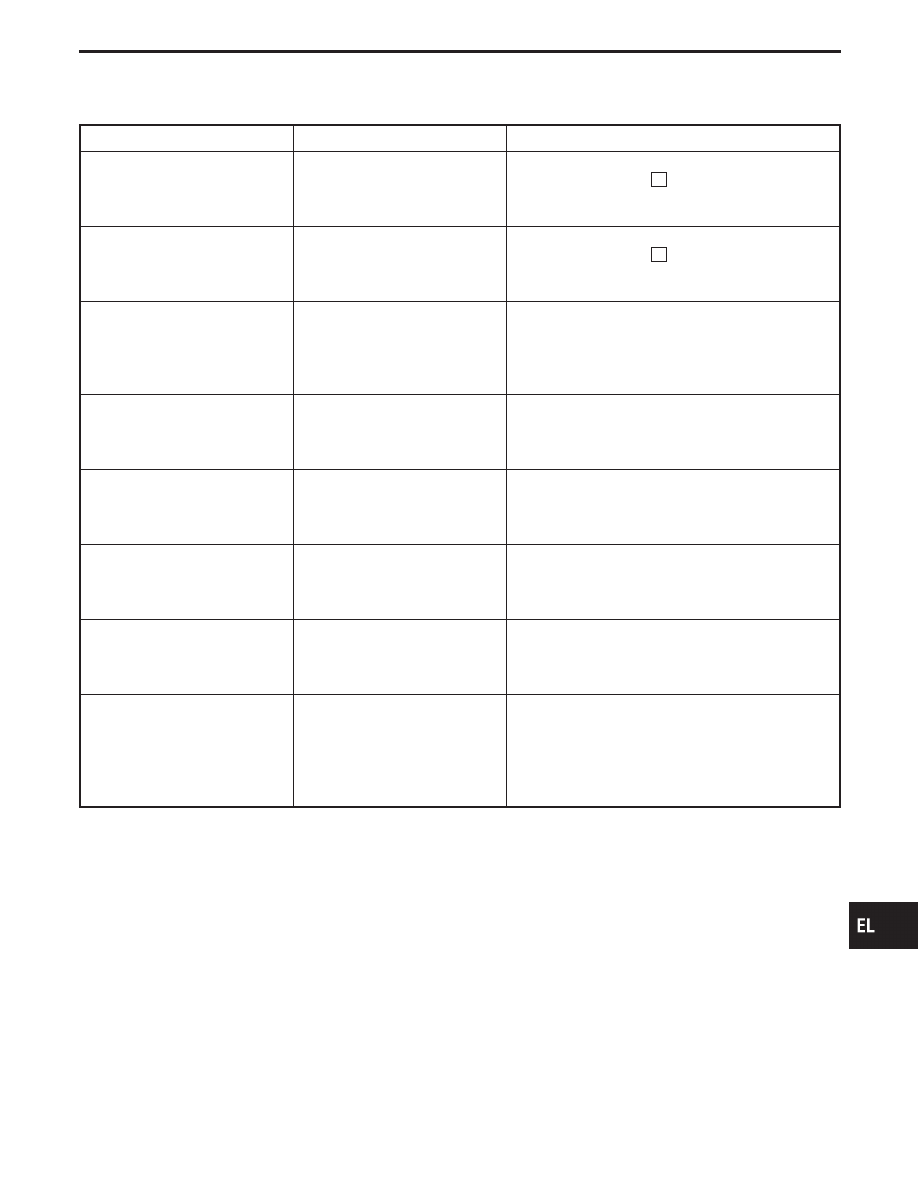
1.
Open the hood.
2.
Adjust the vertical indicator by turning the adjusting screw (ver-
tical direction).
The bubble in the gauge should be centered on the “O” mark
as shown in the figure.
SEL128V
3.
Adjust the horizontal indicator by turning the adjusting screw.
(horizontal direction)
The inner red line should align with the indicator line.
SEL866LA
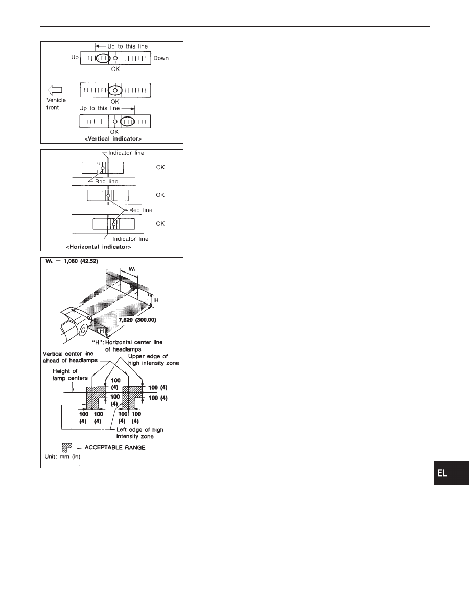
If the vehicle front body has been repaired and/or the headlamp
assembly has been replaced, check aiming. Use the aiming chart
shown in the figure.
I
Upper edge and left edge of high intensity zone should be
within the range shown at left. Adjust headlamps accord-
ingly.
I
Dotted lines in illustration show center of headlamp.
“H”: Horizontal center line of headlamps
“W
L
”: Distance between each headlamp center
GI
MA
EM
LC
EC
FE
AT
PD
FA
RA
BR
ST
RS
BT
HA
IDX
HEADLAMP (FOR U.S.A.) — CONVENTIONAL TYPE —
Aiming Adjustment/Conventional Type (Cont’d)
EL-77

Component Parts and Harness Connector
Location
SEL139Y
System Description
Power is supplied at all times
I
through 15A fuse [No.
54
, located in the fuse, fusible link and relay box]
I
to headlamp relay terminal
q
1
and
I
to headlamp relay terminal
q
7
, and
I
through 15A fuse [No.
53
, located in the fuse, fusible link and relay box]
I
to headlamp relay terminal
q
5
, and
I
through 7.5A fuse [No.
14
, located in the fuse block (J/B)].
I
to BCM terminal
105
.
Power is also supplied at all times
I
to HID relay terminal
q
1
, and
I
through 20A fuse (No.
61
, located in the fuse, fusible link and relay box)
I
to HID relay terminal
q
3
, and
I
through 20A fuse (No.
59
, located in the fuse, fusible link and relay box)
I
to HID relay terminal
q
6
, and
When the ignition switch is in the ACC or ON position, power is supplied
I
through 7.5A fuse [No.
23
, located in the fuse block (J/B)]
I
to BCM terminal
q
60
.
When the ignition switch is in the ON or START position, power is supplied
I
through 7.5A fuse [No.
32
, located in the fuse block (J/B)]
I
to BCM terminal
q
68
.
Ground is supplied
I
to BCM terminals
q
56
and
113
I
to illumination time control switch terminal
q
3
I
through body grounds
M14
and
M47
, and
I
to the lighting switch terminals
q
8
and
q
5
I
through body grounds
E22
and
E36
.
HEADLAMP SWITCH OPERATION
Low beam operation
When the lighting switch is turned to 2ND (LOW or HI) or PASS (“C”) position, ground is supplied
I
to HID relay terminal
q
2
I
from the lighting switch terminal
q
12
.
HEADLAMP (FOR U.S.A.) — XENON TYPE —
EL-78
Нет комментариевНе стесняйтесь поделиться с нами вашим ценным мнением.
Текст