Infiniti Q45 (FY33). Manual — part 321
Trouble Diagnoses
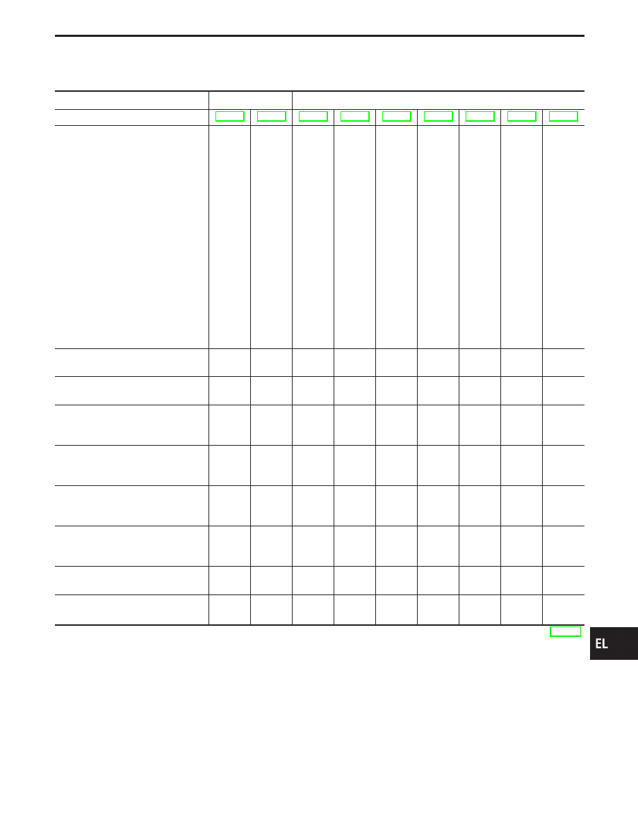
SYMPTOM CHART
PROCEDURE
—
Diagnostic procedure
REFERENCE PAGE
SYMPTOM
Self-diagnosis
in
CONSUL
T
-II
Fail-safe
system
check
DIAGNOSTIC
PROCEDURE
1
(POWER
SUPPL
Y
AND
GROUND
CIRCUIT
CHECK)
DIAGNOSTIC
PROCEDURE
2
(ASCD
HOLD
UNIT
CHECK)
DIAGNOSTIC
PROCEDURE
3
(ASCD
BRAKE/ST
OP
LAMP
SWITCH
CHECK)
DIAGNOSTIC
PROCEDURE
4
(ASCD
STEERING
SWITCH
CHECK)
DIAGNOSTIC
PROCEDURE
5
(VEHICLE
SPEED
SIGNAL
CHECK)
DIAGNOSTIC
PROCEDURE
6
(ASCD
PUMP
CIRCUIT
CHECK)
DIAGNOSTIC
PROCEDURE
7
(ASCD
ACTUA
T
OR/PUMP
CHECK)
ASCD cannot be set. (“SET” indica-
tor lamp does not blink.)
X
X
X
X
X
ASCD cannot be set. (“SET” indica-
tor lamp blinks.
★
1)
X
X
X
X
X
X
Vehicle speed does not decrease
after SET/COAST switch has been
pressed.
X
X
X
Vehicle speed does not return to the
set speed after RESUME/ACCEL
switch has been pressed.
★
2
X
X
X
Vehicle speed does not increase
after RESUME/ACCEL switch has
been pressed.
X
X
X
System is not released after CAN-
CEL switch (steering) has been
pressed.
X
X
X
Large difference between set speed
and actual vehicle speed.
X
X
X
X
Deceleration is greatest immediately
after ASCD has been set.
X
X
X
X
★
1: It indicates that system is in fail-safe. After completing diagnostic procedures, perform “Fail-safe System Check” (EL-274)
to verify repairs.
★
2: If vehicle speed is greater than 48 km/h (30 MPH) after system has been released, pressing RESUME/ACCEL switch returns
vehicle speed to the set speed previously achieved. However, doing so when the ASCD main switch is turned to “OFF”,
vehicle speed will not return to the set speed since the memory is canceled.
GI
MA
EM
LC
EC
FE
AT
PD
FA
RA
BR
ST
RS
BT
HA
IDX
AUTOMATIC SPEED CONTROL DEVICE (ASCD)
EL-275
SEL289UI
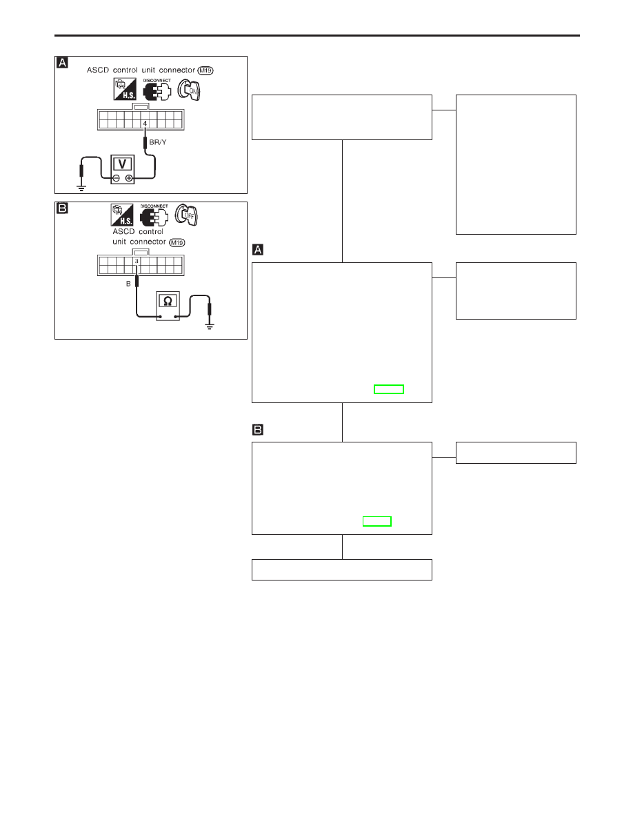
DIAGNOSTIC PROCEDURE 1
(POWER SUPPLY AND GROUND CIRCUIT CHECK)
SEL764UA
1. Turn ignition switch ON.
2. Turn ASCD main switch “ON”.
Does “CRUISE” indicator illuminate?
Yes
E
No
Check the following.
I
ASCD hold unit. Go to
DIAGNOSTIC PROCE-
DURE 2 (ASCD HOLD
UNIT CHECK).
I
Harness for open or
short between ASCD
hold unit and combina-
tion meter
I
“CRUISE” indicator
ground circuit
CHECK POWER SUPPLY CIRCUIT FOR
ASCD CONTROL UNIT.
1. Disconnect ASCD control unit connec-
tor.
2. Turn ignition switch ON.
3. Turn ASCD main switch “ON”.
4. Check voltage between control unit
connector terminal
q
4
and ground.
Does battery voltage exist?
Refer to wiring diagram in EL-266.
Yes
E
No
Check harness for open or
short between ASCD con-
trol unit and ASCD hold
unit.
CHECK GROUND CIRCUIT FOR ASCD
CONTROL UNIT.
Check continuity between ASCD control
unit harness terminal
q
3
and ground.
Does continuity exist?
Refer to wiring diagram in EL-269.
Yes
E
No
Repair harness.
Power supply and ground circuit is OK.
AUTOMATIC SPEED CONTROL DEVICE (ASCD)
Trouble Diagnoses (Cont’d)
H
H
H
EL-276
SEL361VB
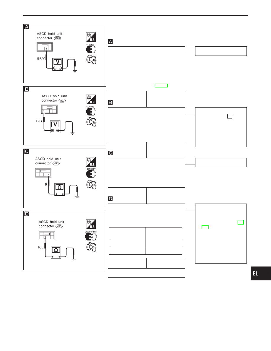
DIAGNOSTIC PROCEDURE 2
(ASCD HOLD UNIT CHECK)
SEL362VB
SEL363VB
SEL364VB
CHECK HOLD UNIT OUTPUT.
1. Turn ignition switch ON.
2. Depress ASCD main switch.
3. Check voltage between hold unit termi-
nal
q
3
and ground.
Does battery voltage exist?
Refer to wiring diagram in EL-266.
No
E
Yes
ASCD hold unit is OK.
CHECK POWER SUPPLY CIRCUIT FOR
HOLD UNIT.
1. Turn ignition switch ON.
2. Check voltage between hold unit termi-
nal
q
1
and ground.
Does battery voltage exist?
Yes
E
No
Check the following.
I
7.5A fuse [No.
32
,
located in the fuse block
(J/B)]
I
Harness for open or
short between fuse and
hold unit
CHECK GROUND CIRCUIT FOR HOLD
UNIT.
Check continuity between hold unit termi-
nal
q
4
and ground.
Does continuity exist?
Yes
E
No
Repair harness.
CHECK MAIN SWITCH INPUT.
1. Disconnect hold unit connector.
2. Check continuity between hold unit
connector terminal
q
2
and ground.
OK
E
NG
Check the following.
I
ASCD steering switch
Refer to “Electrical Com-
ponents Inspection” (EL-
283).
I
Harness for open or
short between ASCD
hold unit and ASCD
steering switch
I
ASCD steering switch
ground circuit
Replace ASCD hold unit.
Condition of main
switch
Continuity
Pressed
Yes
Released
No
GI
MA
EM
LC
EC
FE
AT
PD
FA
RA
BR
ST
RS
BT
HA
IDX
AUTOMATIC SPEED CONTROL DEVICE (ASCD)
Trouble Diagnoses (Cont’d)
H
H
H
H
EL-277
SEL513W
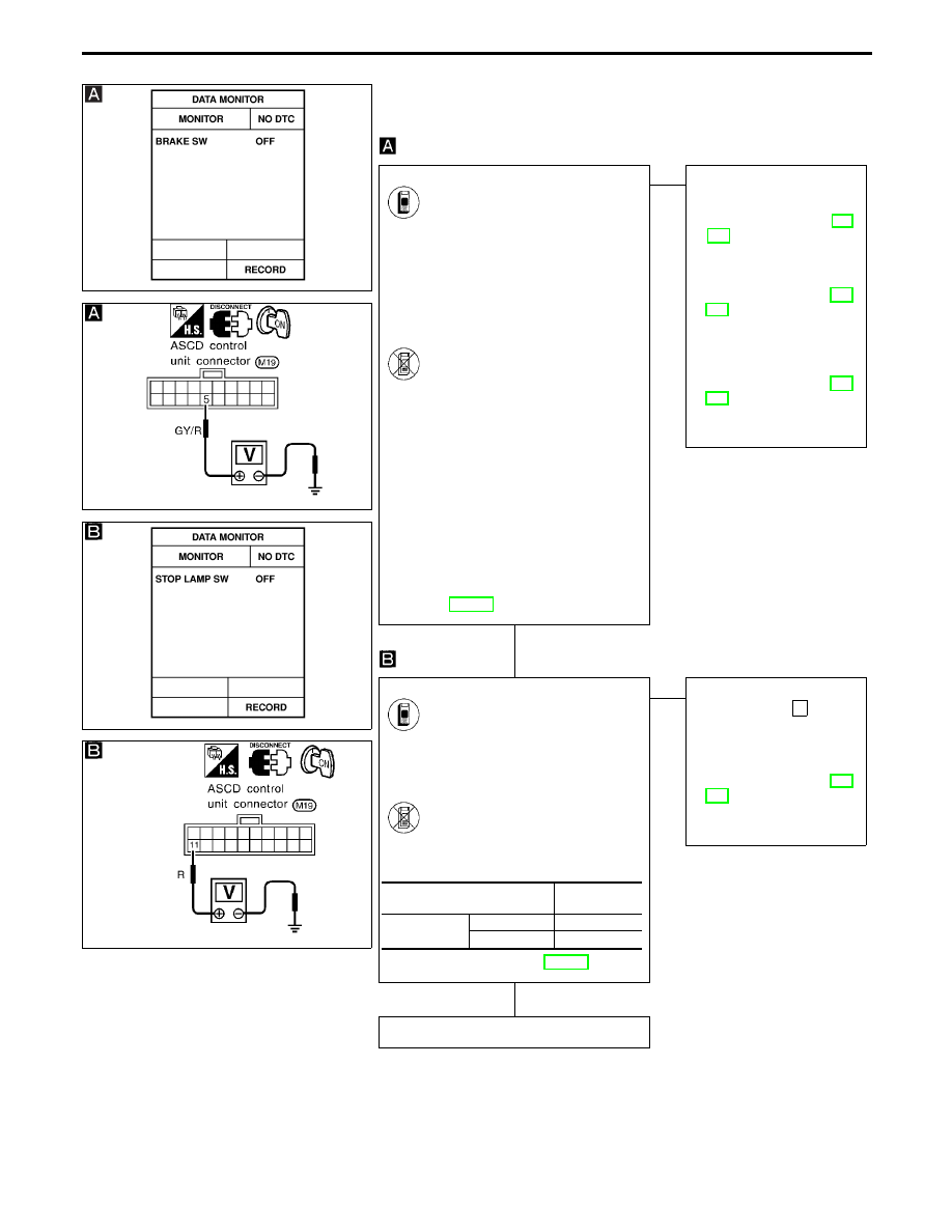
DIAGNOSTIC PROCEDURE 3
(ASCD BRAKE/STOP LAMP SWITCH CHECK)
SEL765UI
SEL514W
SEL759UA
CHECK ASCD BRAKE SWITCH INPUT.
See “BRAKE SW” in “Data moni-
tor” mode.
When brake pedal is depressed or
A/T selector lever is in “N” or “P”
range:
BRAKE SW
OFF
When brake pedal is released and
A/T selector lever is not in “N” or
“P” range:
BRAKE SW
ON
-------------------------------------------------------------------------------------------------------------------------------------- OR --------------------------------------------------------------------------------------------------------------------------------------
1. Disconnect ASCD control unit
connector.
2. Turn ignition switch ON.
3. Turn ASCD main switch “ON”.
4. Check voltage between control
unit connector terminal
q
5
and
ground.
When brake pedal is depressed
or A/T selector lever is in “N” or
“P” range:
Approx. 0V
When brake pedal is released
and A/T selector lever is not in
“N” or “P” range:
Battery voltage should exist.
Refer to wiring diagram in
EL-268.
OK
E
NG
Check the following.
I
ASCD brake switch
Refer to “Electrical Com-
ponents Inspection” (EL-
283).
I
Park/Neutral position
switch
Refer to “Electrical Com-
ponents Inspection” (EL-
283).
I
Park/Neutral position
relay
I
Diode
Refer to “Electrical Com-
ponents Inspection” (EL-
283).
I
Harness for open or
short
CHECK STOP LAMP SWITCH INPUT.
See “STOP LAMP SW” in “Data
monitor” mode.
When brake pedal is released:
STOP LAMP SW
OFF
When brake pedal is depressed:
STOP LAMP SW
ON
-------------------------------------------------------------------------------------------------------------------------------------- OR --------------------------------------------------------------------------------------------------------------------------------------
1. Disconnect ASCD control unit
connector.
2. Check voltage between ASCD
control unit terminal
q
11
and
ground.
Refer to wiring diagram in EL-267.
OK
E
NG
Check the following.
I
15A fuse [No.
37
,
located in the fuse block
(J/B)]
I
Stop lamp switch
Refer to “Electrical Com-
ponents Inspection” (EL-
283).
I
Harness for open or
short.
ASCD brake/stop lamp switch is OK.
Condition
Voltage
V
Stop lamp
switch
Depressed
Approx. 12
Released
0
AUTOMATIC SPEED CONTROL DEVICE (ASCD)
Trouble Diagnoses (Cont’d)
H
H
EL-278
Нет комментариевНе стесняйтесь поделиться с нами вашим ценным мнением.
Текст