Infiniti Q45 (FY33). Manual — part 344
SEL527W
DIAGNOSTIC PROCEDURE 3
SEL525W
SEL505W
SEL257V
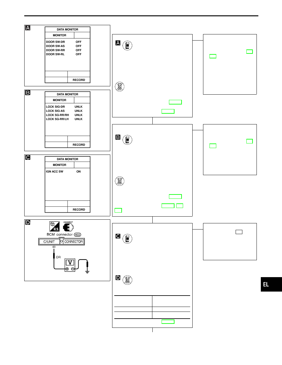
CHECK DOOR SWITCH INPUT SIGNAL.
CONSULT-II
See “DOOR SW” in DATA MONITOR
mode.
When door is open:
DOOR SW
ON
When door is closed:
DOOR SW
OFF
-------------------------------------------------------------------------------------------------------------------------------------- OR --------------------------------------------------------------------------------------------------------------------------------------
ON BOARD
Check all doors switches in Switch moni-
tor (Mode II) mode.
(Refer to On board Diagnosis, EL-299.)
Refer to wiring diagram in EL-359.
OK
E
NG
Check the following.
I
Door switch
Refer to “Electrical Com-
ponents Inspection” (EL-
373).
I
Door switch ground con-
dition (Front door) or
door switch ground cir-
cuit (Rear door)
I
Harness for open or
short between BCM and
door switch
CHECK DOOR UNLOCK SENSOR
INPUT SIGNAL.
CONSULT-II
See “LOCK SIG” in DATA MONITOR
mode.
When door is locked:
LOCK SIG
LOCK
When door is unlocked:
LOCK SIG
UNLK
-------------------------------------------------------------------------------------------------------------------------------------- OR --------------------------------------------------------------------------------------------------------------------------------------
ON BOARD
Check door lock knob operation in Switch
monitor (Mode II) mode.
(Refer to On board Diagnosis, EL-299.)
Refer to wiring diagram in EL-360, or
362.
OK
E
NG
Check the following.
I
Door unlock sensor
Refer to “Electrical Com-
ponents Inspection” (EL-
373).
I
Door unlock sensor
ground circuit
I
Harness for open or
short between LCU and
unlock sensor
CHECK IGNITION SWITCH “ACC” CIR-
CUIT.
CONSULT-II
See “IGN ACC SW” in DATA MONITOR
mode.
When ignition switch is ACC or ON:
IGN ACC SW
ON
When ignition switch is OFF:
IGN ACC SW
OFF
-------------------------------------------------------------------------------------------------------------------------------------- OR --------------------------------------------------------------------------------------------------------------------------------------
TESTER
Check voltage between BCM terminal
q
60
and ground.
Refer to wiring diagram in EL-357.
OK
E
NG
Check the following.
I
7.5A fuse [No. 23 ,
located in fuse block
(J/B)]
I
Harness for open or
short between BCM and
fuse
q
A
Condition of ignition
switch
Voltage V
ACC or ON
Approx. 12
OFF
0
GI
MA
EM
LC
EC
FE
AT
PD
FA
RA
BR
ST
RS
BT
HA
IDX
MULTI-REMOTE CONTROL SYSTEM — IVMS
Trouble Diagnoses (Cont’d)
H
H
H
EL-367
SEL532W
SEL916V
q
A
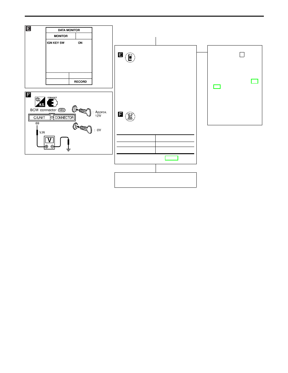
CHECK KEY SWITCH INPUT SIGNAL.
CONSULT-II
See “IGN KEY SW” in DATA MONITOR
mode.
When key is inserted in ignition key cylin-
der:
IGN KEY SW
ON
When key is removed from ignition key
cylinder:
IGN KEY SW
OFF
-------------------------------------------------------------------------------------------------------------------------------------- OR --------------------------------------------------------------------------------------------------------------------------------------
TESTER
Check voltage between BCM terminals
q
69
and ground.
Refer to wiring diagram in EL-358.
OK
E
NG
Check the following.
I
10A fuse [No.
28
,
located in fuse block
(J/B)]
I
Key switch
Refer to “Electrical Com-
ponents Inspection” (EL-
373).
I
Harness for open or
short between key switch
and fuse
I
Harness for open or
short between BCM and
key switch
Check operation parts in multi-remote
control system for function.
Condition
Voltage V
Key is inserted
Approx. 12
Key is removed
0
MULTI-REMOTE CONTROL SYSTEM — IVMS
Trouble Diagnoses (Cont’d)
H
H
EL-368
SEL528W
DIAGNOSTIC PROCEDURE 4
SEL258V
SEL747UC
SEL748UB
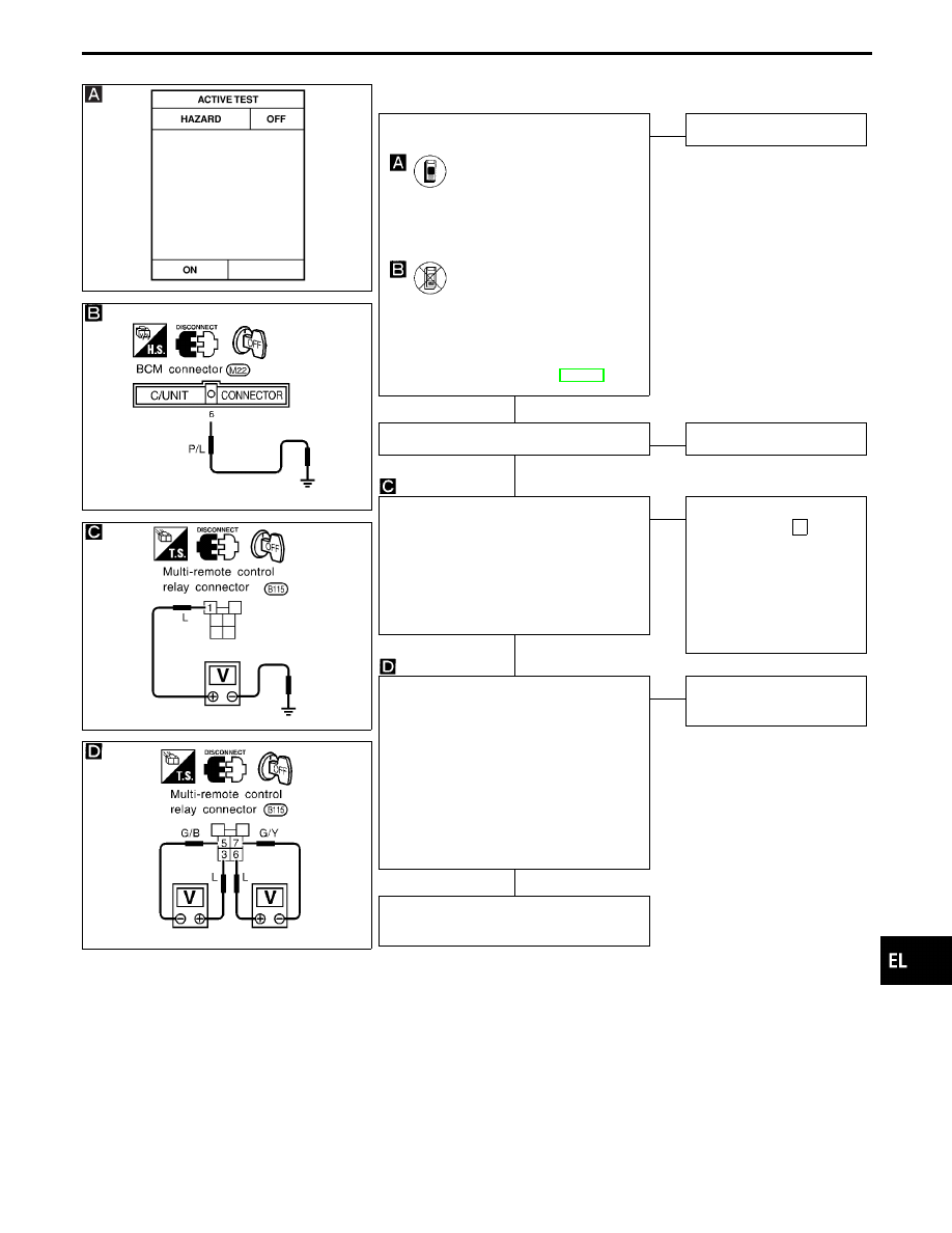
CHECK HAZARD INDICATOR OPERA-
TION.
CONSULT-II
See “HAZARD” in ACTIVE TEST mode.
Perform operation shown on display.
Hazard warning lamp should illuminate.
-------------------------------------------------------------------------------------------------------------------------------------- OR --------------------------------------------------------------------------------------------------------------------------------------
1. Disconnect control unit connector.
2. Apply ground to BCM terminal
q
6
.
Does hazard indicator illuminate?
Refer to wiring diagram in EL-358.
No
E
Yes
Hazard indicator is OK.
Check multi-remote control relay.
OK
E
NG
Replace.
CHECK POWER SUPPLY FOR MULTI-
REMOTE CONTROL RELAY.
1. Disconnect multi-remote control relay
connector.
2. Check voltage between terminal
q
1
and
ground.
Battery voltage should exist.
OK
E
NG
Check the following.
I
10A fuse [No.
13
,
located in fuse block
(J/B)]
I
Harness for open or
short between multi-
remote control relay and
fuse
CHECK MULTI-REMOTE CONTROL
RELAY CIRCUIT.
1. Disconnect multi-remote control relay
connector.
2. Check voltage between terminals
q
3
and
q
5
.
Battery voltage should exist.
3. Check voltage between terminals
q
6
and
q
7
.
Battery voltage should exist.
OK
E
NG
Check harness for open or
short.
Check harness for open or short between
BCM and multi-remote control relay.
GI
MA
EM
LC
EC
FE
AT
PD
FA
RA
BR
ST
RS
BT
HA
IDX
MULTI-REMOTE CONTROL SYSTEM — IVMS
Trouble Diagnoses (Cont’d)
H
H
H
H
EL-369
SEL945W
SEL258VB
DIAGNOSTIC PROCEDURE 5
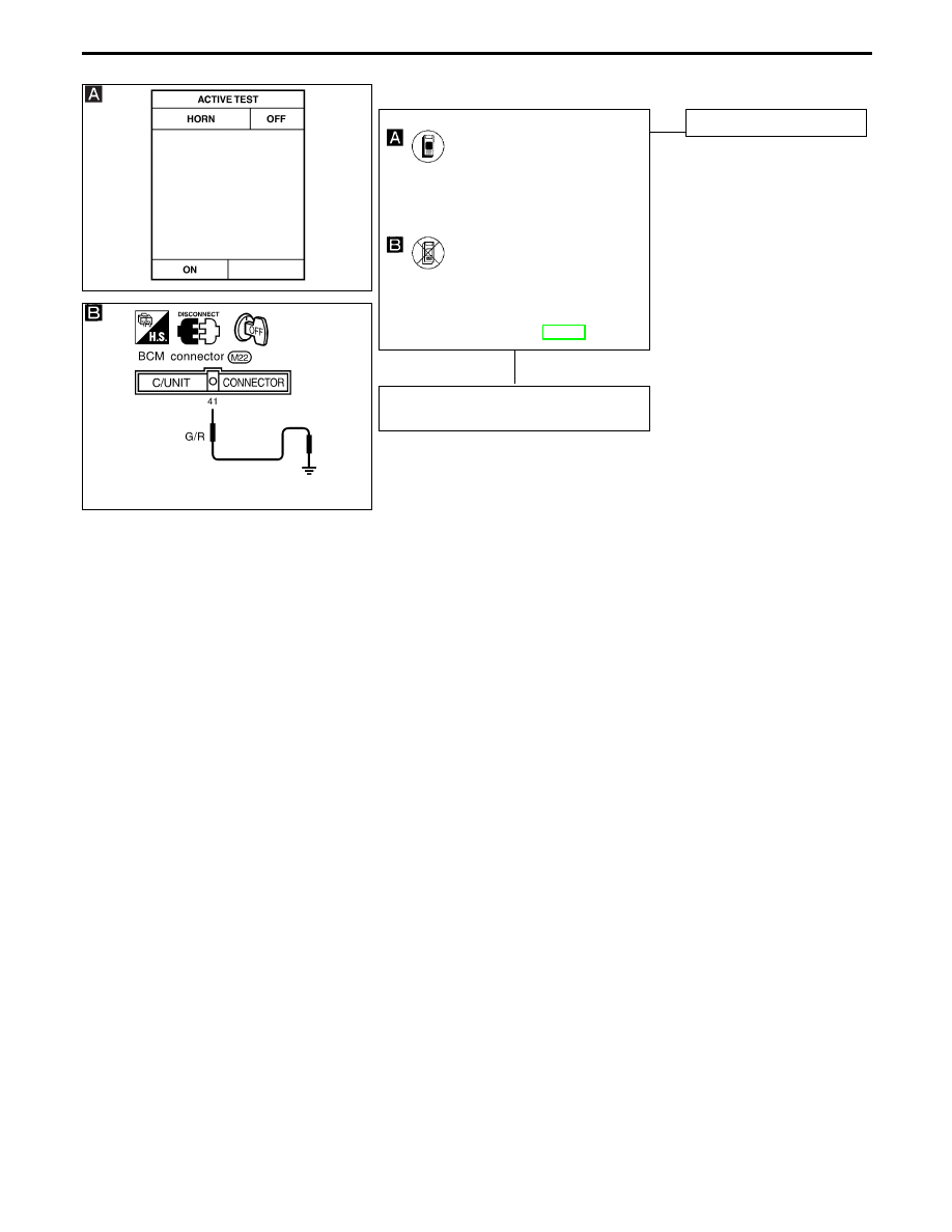
CHECK HORN CHIRP OPERATION.
CONSULT-II
See “HORN” in ACTIVE TEST mode. Per-
form operation shown on display.
Horn should sound.
-------------------------------------------------------------------------------------------------------------------------------------- OR --------------------------------------------------------------------------------------------------------------------------------------
1. Disconnect control unit connector.
2. Apply ground to BCM terminal
q
41
.
Does horn sound?
Refer to wiring diagram in EL-358.
No
E
Yes
Horn chirp operation is OK.
Check harness for open or short between
BCM and horn relay.
MULTI-REMOTE CONTROL SYSTEM — IVMS
Trouble Diagnoses (Cont’d)
H
EL-370
Нет комментариевНе стесняйтесь поделиться с нами вашим ценным мнением.
Текст