Infiniti Q45 (FY33). Manual — part 442
WARNING:
When replacing fuel line parts, be sure to observe the following:
I
Put a “
CAUTION:
FLAMMABLE” sign in workshop.
I
Be sure to furnish workshop with a CO
2
fire extinguisher.
I
Do not smoke while servicing fuel system. Keep open flames and sparks away from work area.
I
Be sure to disconnect battery ground cable before conducting operations.
I
Drain fuel from Fuel Tank and put drained fuel in an explosion-proof container and put lid on
securely.
CAUTION:
I
Before disconnecting fuel hose, release fuel pressure from fuel line. Refer to MA section, “Chang-
ing Fuel Filter”.
I
Do not disconnect any fuel line unless absolutely necessary.
I
Plug hose and pipe openings to prevent entry of dust or dirt.
I
Always replace O-ring and clamps with new ones.
I
Do not kink or twist hose and tube when they are installed.
I
Do not tighten hose clamps excessively to avoid damaging hoses.
I
Tighten bolts to specified torque.
I
After installation, run engine and check for fuel leaks at connections.
I
Use only a genuine fuel filler cap as a replacement.
I
For inspection, refer to EC section, “On Board Refueling Vapor Recovery (ORVR)”.
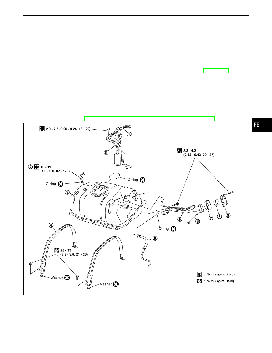
SFE589A
q
1
Fuel tube
q
2
EVAP purge line
q
3
Fuel tank
q
4
Fuel tank tightening band
q
5
Filler tube
q
6
Drain hose
q
7
Grommet
q
8
Fuel filler cap
q
9
Cover
q
10
Refueling EVAP vapor line
q
11
Fuel level sensor unit and fuel
pump
GI
MA
EM
LC
EC
AT
PD
FA
RA
BR
ST
RS
BT
HA
EL
IDX
FUEL SYSTEM
FE-5
SFE558A
Fuel Tank
SFE562A
REMOVAL
1.
Release fuel pressure from fuel line.
Refer to EC section, “Fuel Pressure Release”.
2.
Disconnect battery ground cable.
3.
Drain fuel from fuel tank.
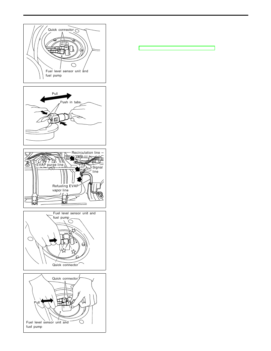
4.
Disconnect electrical connector.
5.
Remove the quick connector as follows.
a.
Put mating marks on tubes and connectors for correct instal-
lation.
b.
Hold the sides of the connector, push in tabs, and pull out the
tube inserted in the retainer.
CAUTION:
I
The tube can be removed when the push in tabs are com-
pletely depressed. Do not twist it more than necessary.
I
Do not use any tools to remove the quick connector.
SFE590A
6.
Disconnect EVAP purge line, recirculation line, signal line and
refueling EVAP vapor line at fuel tank side.
7.
Remove fuel tank mounting band bolts while supporting fuel
tank.
8.
Remove fuel tank.
SFE560A
INSTALLATION
To install, reverse the removal procedure. Connect the quick con-
nector as follows:
I
Align mating marks on tubes and connectors for correct instal-
lation.
I
Align push in tabs with retainer openings.
I
Insert tube into the center of the connector until you hear a
click.
SFE561A
After connecting quick connector, make sure the connection is
firmly made using the following method.
I
Pull on the fuel tube and connector to make sure they are firmly
connected.
I
Start the engine, increase engine speed and verify that there
are no leaks.
FUEL SYSTEM
FE-6
SFE180A
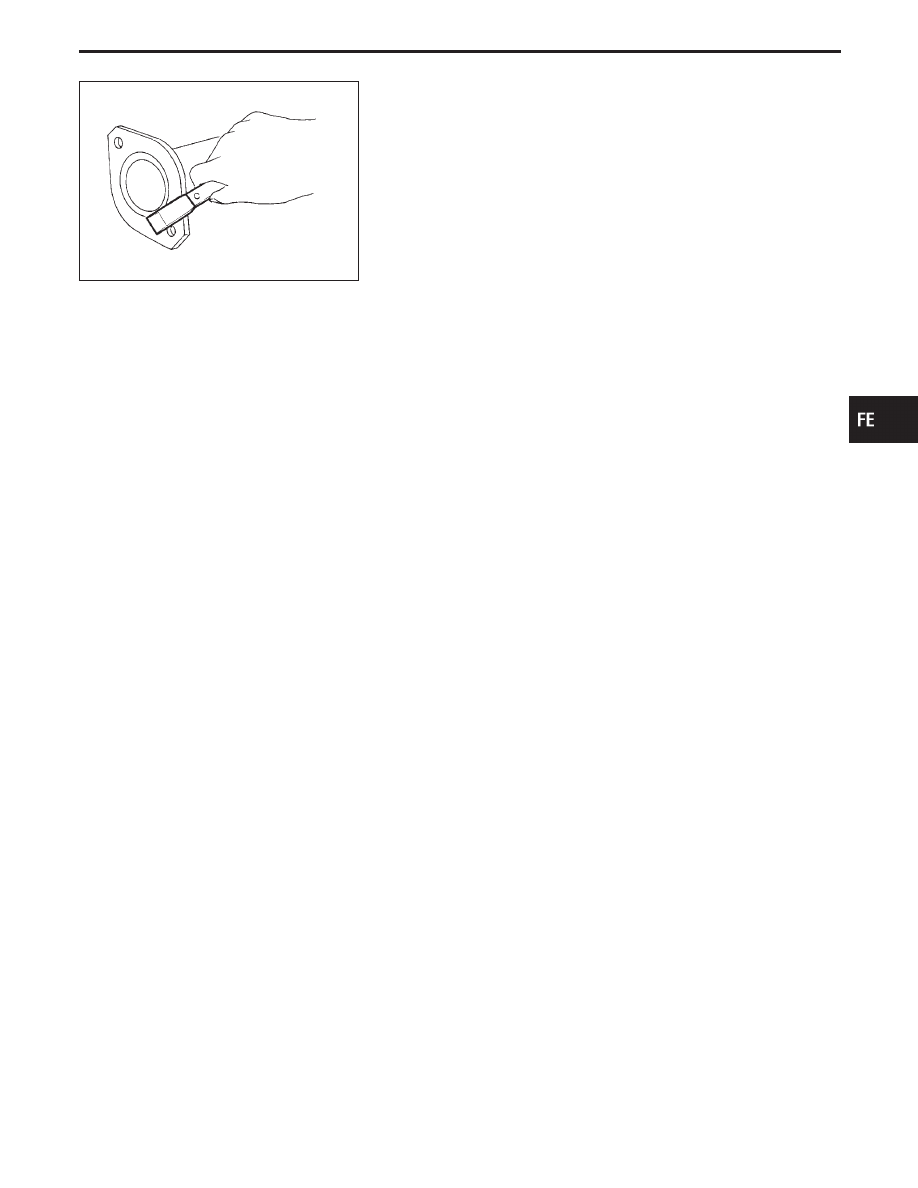
CAUTION:
I
Always replace exhaust gaskets with new ones when
reassembling. If gasket is left on flange surface, scrape off
completely as shown at left.
I
With engine running, check all tube connections for
exhaust gas leaks, and entire system for unusual noises.
I
Check to ensure that mounting brackets and mounting
insulators are installed properly free from undue stress.
Improper installation could result in excessive noise or
vibration.
I
Discard any heated oxygen sensor which has been
dropped from a height of more than 0.5 m (19.7 in) onto a
hard surface such as a concrete floor; use a new one.
I
Before installing a new oxygen sensor, clean exhaust sys-
tem threads using oxygen sensor thread cleaner tool,
J-43897-18 or J-43897-12, and apply anti-seize lubricant.
I
Do not overtorque the oxygen sensor. Doing so may
cause damage to the oxygen sensor, resuiting in the MIL
coming on.
GI
MA
EM
LC
EC
AT
PD
FA
RA
BR
ST
RS
BT
HA
EL
IDX
EXHAUST SYSTEM
FE-7
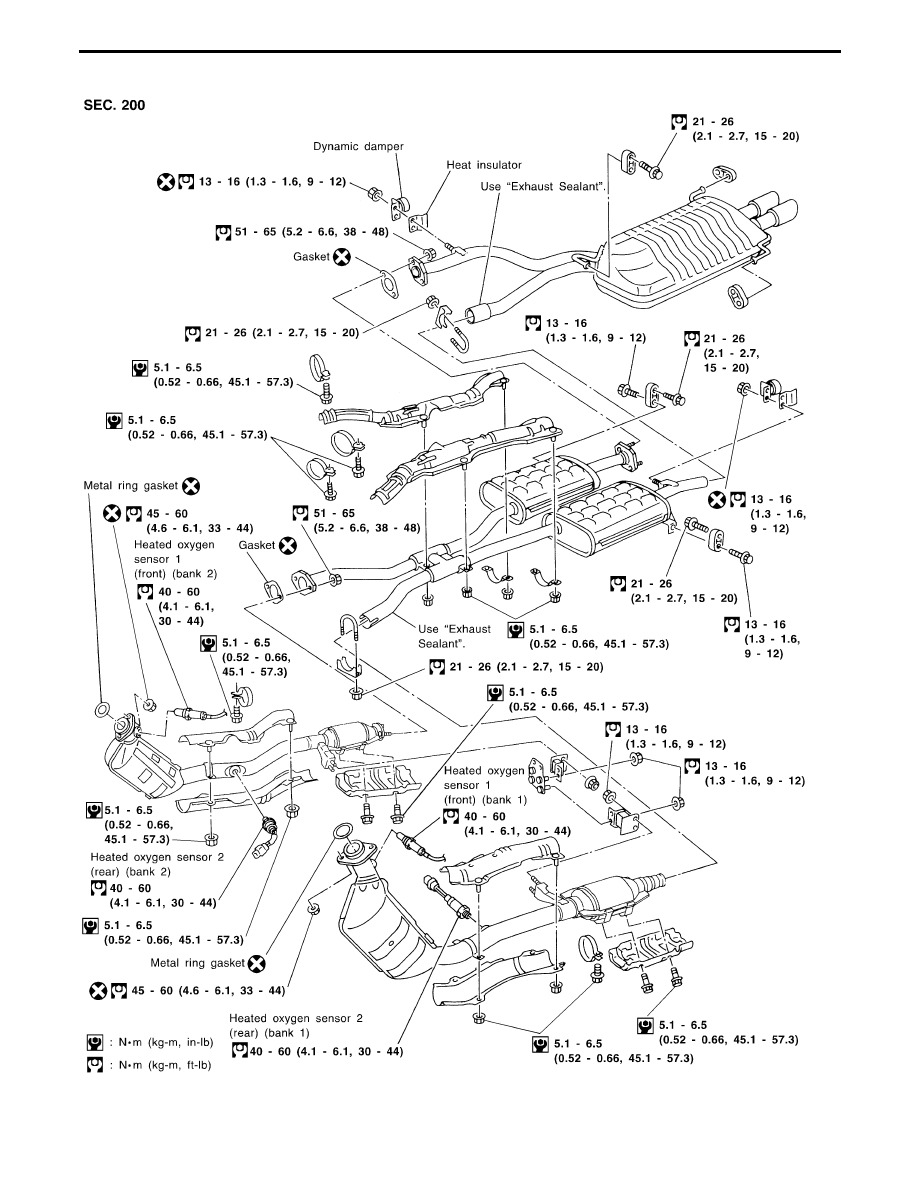
SFE676A
EXHAUST SYSTEM
FE-8
Нет комментариевНе стесняйтесь поделиться с нами вашим ценным мнением.
Текст