Infiniti Q45 (FY33). Manual — part 338
DESCRIPTION
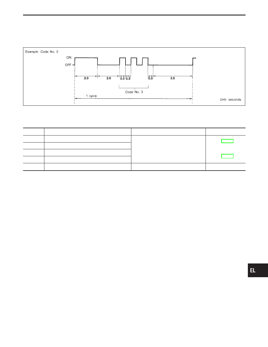
In this mode, a malfunction code is indicated by the number of flashes from the front map lamps and step
lamps as shown below:
SEL472T
After indicator lamp turns ON for 2 seconds and then turns OFF, it flashes to indicate a malfunction code.
For example, the indicator lamp goes on and off for 0.5 seconds three times. This indicates malfunction code
“3”.
MALFUNCTION CODE TABLE
Code No.
Detected items
Diagnostic procedure
Reference page
1
Driver door lock actuator/unlock sensor
Procedure 5 (Door unlock sensor check)
Procedure 6 (Door lock actuator check)
2
Passenger door lock actuator/unlock sensor
3
Rear RH door lock actuator/unlock sensor
4
Rear LH door lock actuator/unlock sensor
9
No malfunction in the above items
—
—
GI
MA
EM
LC
EC
FE
AT
PD
FA
RA
BR
ST
RS
BT
HA
IDX
POWER DOOR LOCK — IVMS
On board Diagnosis — Mode III (Power door
lock operation) (Cont’d)
EL-343
Trouble Diagnoses
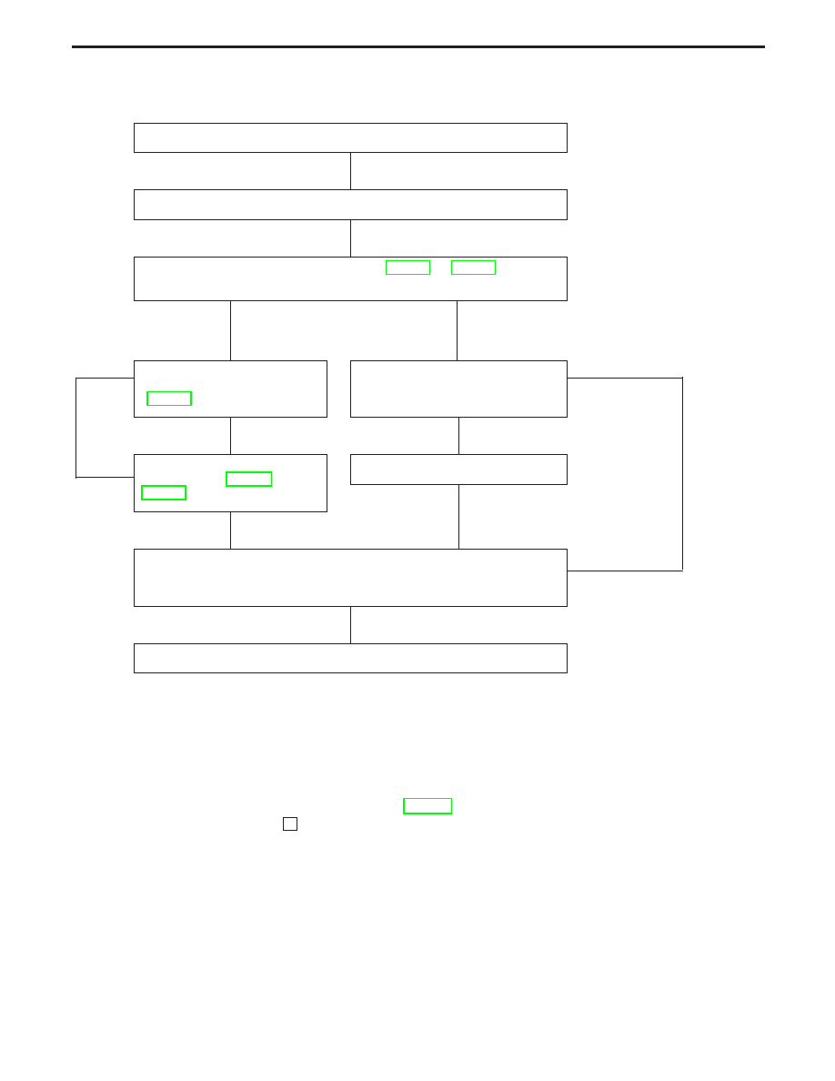
WORK FLOW
CHECK IN
LISTEN TO CUSTOMER COMPLAINT
IVMS COMMUNICATION DIAGNOSIS (EL-291 or EL-297)
Do self-diagnostic results exist?
Yes
No
SYMPTOM
BASIS
E
Repair/Replace according to
the self-diagnostic results.
(EL-293)
Perform diagnostic procedure
according to the symptom chart
on the next page.
F
NG
IVMS COMMUNICATION
DIAGNOSIS (EL-291 or
EL-297)
OK
H
REPAIR/REPLACE
FINAL CHECK
Confirm that the malfunction is completely fixed by operating the
system.
OK
NG
CHECK OUT
NOTICE:
I
When LCU connectors are disconnected for more than 1 minute such as during trouble diagnoses,
the “disconnected” data will be memorized by the BCM. (While BCM memorizes the “disconnected”
data, IVMS communication diagnosis of CONSULT-II will display “PAST NO RESPONSE”.)
Therefore, after reconnecting the LCU connectors, erase the memory.
I
To erase the memory, perform the procedure below.
Erase the memory with CONSULT-II (Refer to EL-291.) or turn the ignition switch to “OFF” position
and remove 7.5A fuse [No.
14
located in the fuse block (J/B)].
POWER DOOR LOCK — IVMS
H
H
H
H
H
H
H
H
EL-344
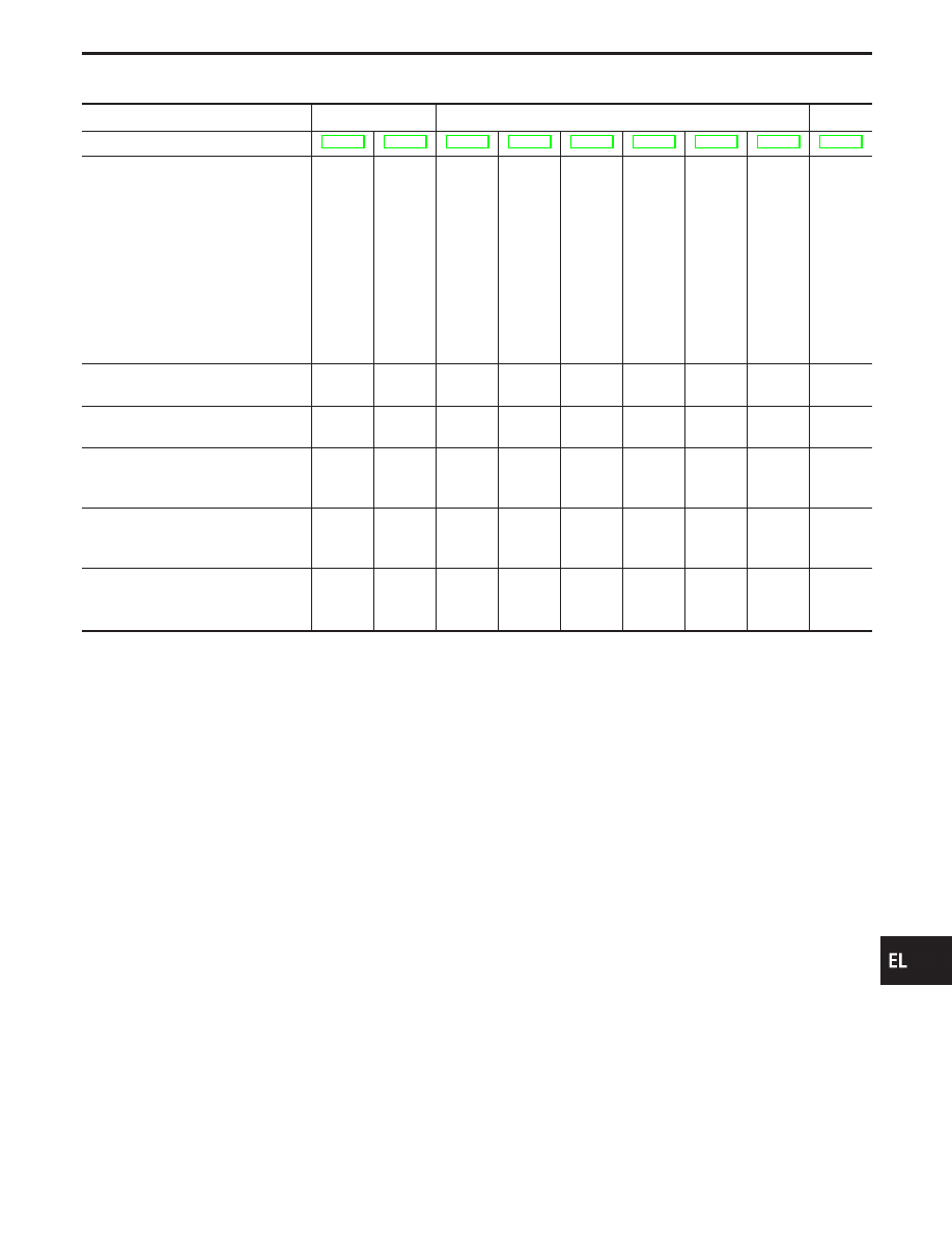
SYMPTOM CHART
PROCEDURE
Self-diagnosis
Diagnostic procedure
—
REFERENCE PAGE
SYMPTOM
CONSUL
T
-II
On
board
diagnosis
(Mode
III)
Procedure
1
(Door
switch
check)
Procedure
2
(Key
switch
check)
Procedure
3
(Lock
&
unlock
switch
check)
Procedure
4
(Door
key
cylinder
switch
check)
Procedure
5
(Door
unlock
sensor
check)
Procedure
6
(Door
lock
actuator
check)
W
ake-up
diagnosis
Key reminder door system does not
operate properly.
X
X
X
X
X
X
Specific door lock actuator does not
operate.
X
X
X
X
Power door lock does not operate
with door lock & unlock switch on
power window main switch.
X
X
X
X
(LCU01)
Power door lock does not operate
with front door key cylinder opera-
tion.
X
X
X
X
(LCU01,
LCU02)
Power door lock does not operate
with front door lock knob switch.
X
X
X
X
(LCU01,
LCU02)
GI
MA
EM
LC
EC
FE
AT
PD
FA
RA
BR
ST
RS
BT
HA
IDX
POWER DOOR LOCK — IVMS
Trouble Diagnoses (Cont’d)
EL-345
SEL524W
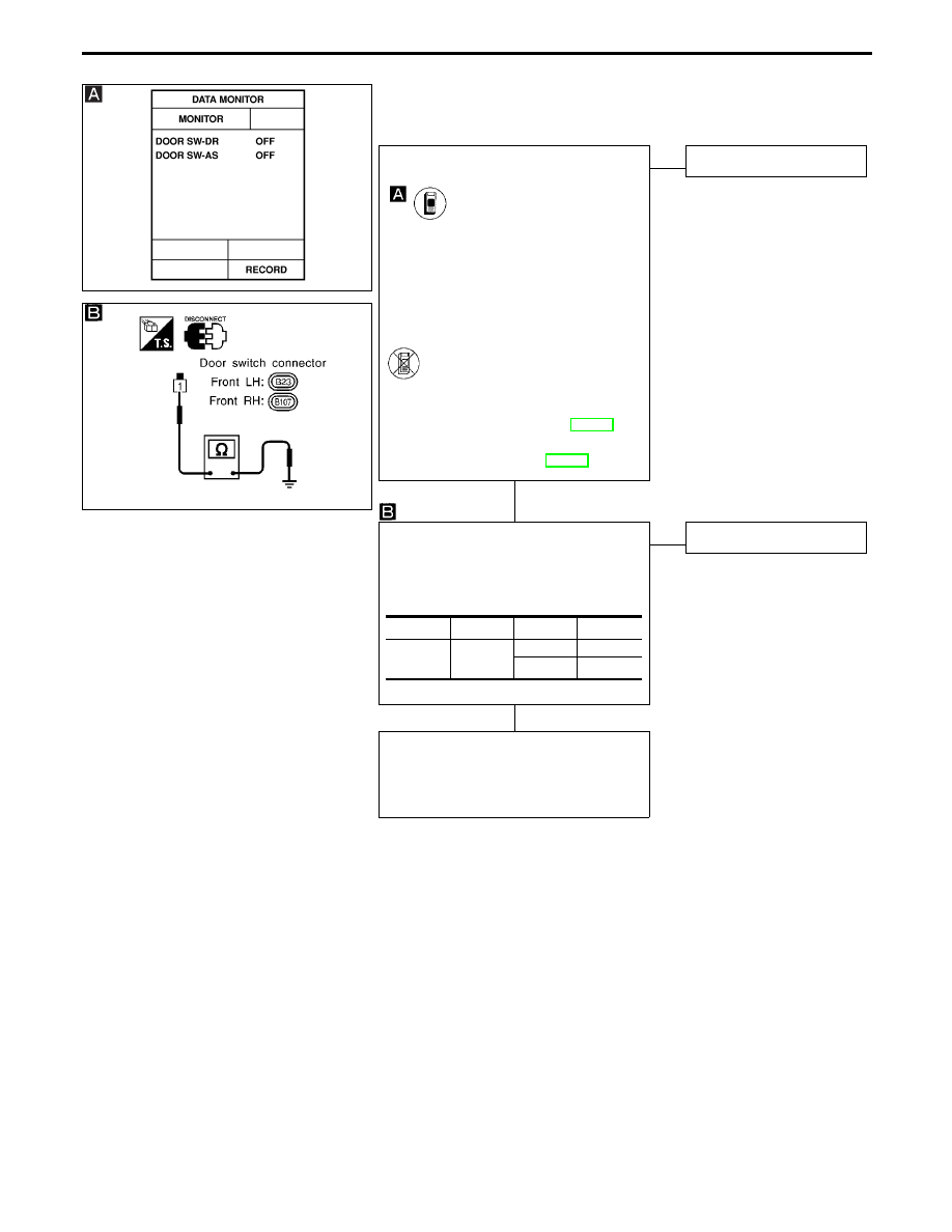
DIAGNOSTIC PROCEDURE 1
(Front door switch check)
SEL914U
CHECK FRONT DOOR SWITCH INPUT
SIGNAL.
CONSULT-II
See “DOOR SW” in DATA MONITOR
mode.
When door is open:
DOOR SW
ON
When door is closed:
DOOR SW
OFF
-------------------------------------------------------------------------------------------------------------------------------------- OR --------------------------------------------------------------------------------------------------------------------------------------
ON BOARD
Check front door switches in Switch moni-
tor (Mode II) mode.
(Refer to On board Diagnosis, EL-299.)
Refer to wiring diagram in EL-335.
NG
E
OK
Door switch is OK.
CHECK DOOR SWITCH.
1. Disconnect door switch connector.
2. Check continuity between terminal and
switch body ground.
OK
E
NG
Replace door switch.
Check the following.
I
Door switch ground condition
I
Harness for open or short between door
switch and BCM
Terminals
Condition
Continuity
Front door
switch
q
1
-
Ground
Pressed
No
Released
Yes
POWER DOOR LOCK — IVMS
Trouble Diagnoses (Cont’d)
H
H
EL-346
Нет комментариевНе стесняйтесь поделиться с нами вашим ценным мнением.
Текст