Infiniti Q45 (FY33). Manual — part 227
SEF594U
SEF765X
SEF597U
SEF406W
SEF394WA
q
B
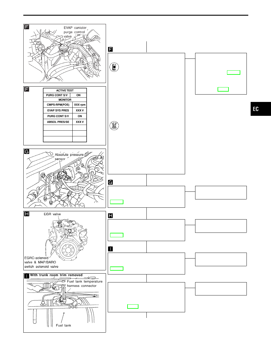
CHECK COMPONENT (EVAP canister
purge control solenoid valve).
1. Disconnect vacuum hose to
EVAP canister purge control
solenoid valve.
2. Start engine.
3. Perform “PURG CONT S/V” in
“ACTIVE TEST” mode.
4. Select “ON” on CONSULT-II
screen to turn on “PURG CONT
S/V”.
5. Check vacuum hose for vacuum
when revving engine up to 2,000
rpm.
Vacuum should exist.
-------------------------------------------------------------------------------------------------------------------------------------- OR --------------------------------------------------------------------------------------------------------------------------------------
1. Start engine and warm it up to
normal operating temperature.
2. Stop engine.
3. Disconnect vacuum hose to
EVAP canister purge control
valve.
4. Start engine and let it idle for at
least 60 seconds.
5. Check vacuum hose for vacuum
when revving engine up to 2,000
rpm.
Vacuum should exist.
OK
E
NG
Check the following.
I
EVAP canister purge con-
trol solenoid valve
Refer to “COMPONENTS
INSPECTION”, EC-440.
I
Vacuum hoses for clog-
ging or disconnection.
Refer to “Vacuum Hose
Drawing”, EC-29.
CHECK COMPONENT
(Absolute pressure sensor).
Refer to “COMPONENT INSPECTION”,
EC-442.
OK
E
NG
Replace absolute pressure
sensor.
CHECK COMPONENT
(MAP/BARO switch solenoid valve).
Refer to “COMPONENT INSPECTION”,
EC-442.
OK
E
NG
Replace MAP/BARO
switch solenoid valve.
CHECK COMPONENT
(Fuel tank temperature sensor).
Refer to “COMPONENT INSPECTION”,
EC-443.
OK
E
NG
Replace fuel tank tempera-
ture sensor.
CHECK COMPONENT.
Check EVAP purge line (pipe, rubber tube,
fuel tank and EVAP canister) for cracks or
improper connection.
Refer to “Evaporative Emission Line
Drawing”, EC-29.
OK
E
NG
Repair or reconnect the
hose.
q
C
(Go to next page.)
GI
MA
EM
LC
FE
AT
PD
FA
RA
BR
ST
RS
BT
HA
EL
IDX
TROUBLE DIAGNOSIS FOR DTC P1440
Evaporative Emission (EVAP) Control System
(Small Leak) (Positive Pressure) (Cont’d)
H
H
H
H
H
H
EC-437
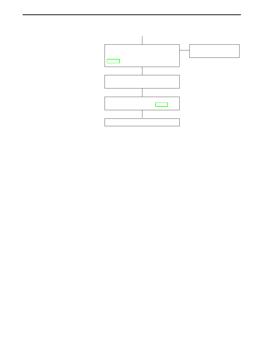
q
C
CHECK COMPONENT
(EVAP control system pressure sensor).
Refer to “COMPONENT INSPECTION”,
EC-325.
OK
E
NG
Replace EVAP control sys-
tem pressure sensor.
Clean EVAP purge line (pipe and rubber
tube) using air blower.
Perform “TROUBLE DIAGNOSIS FOR
INTERMITTENT INCIDENT”, EC-117.
INSPECTION END
TROUBLE DIAGNOSIS FOR DTC P1440
Evaporative Emission (EVAP) Control System
(Small Leak) (Positive Pressure) (Cont’d)
H
H
H
H
EC-438
SEF353Q
SEC049C
SEF763P
SEF593U
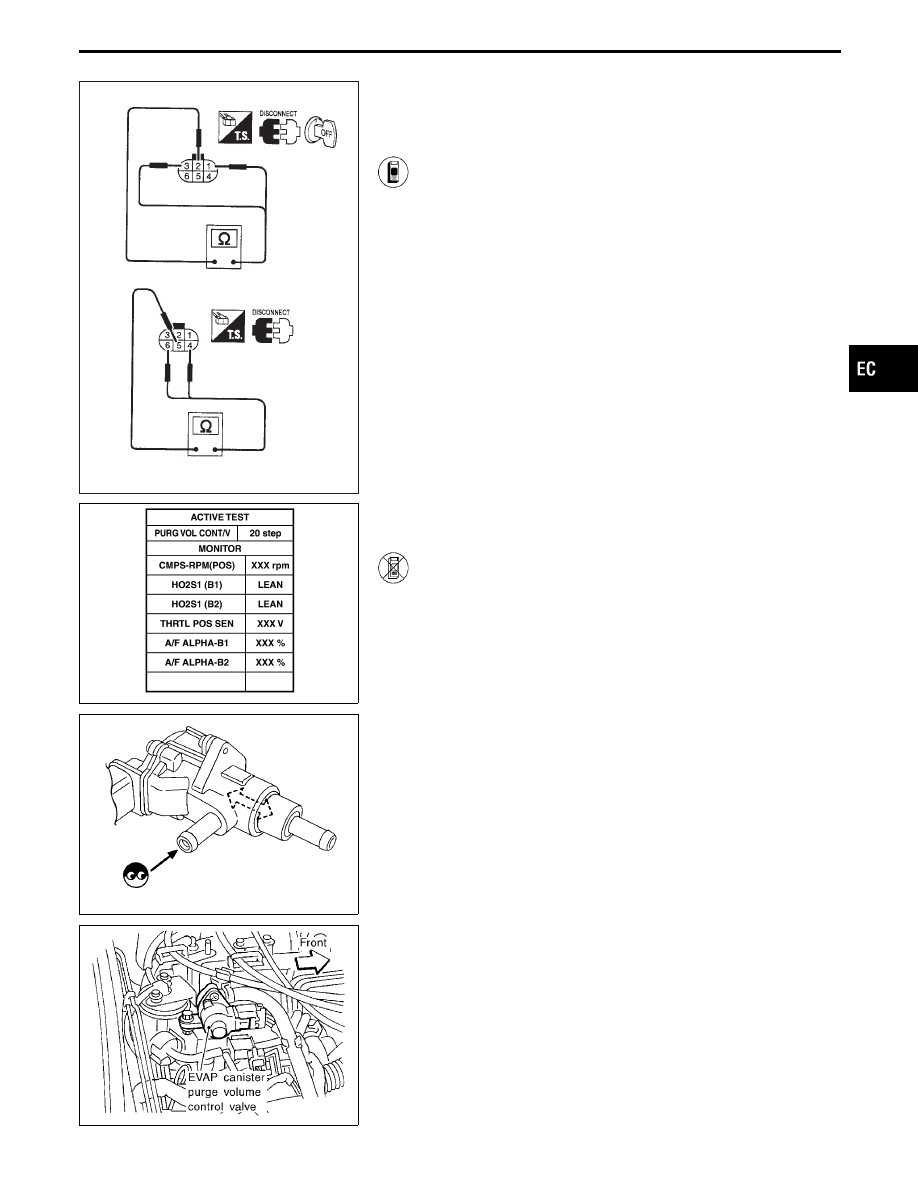
COMPONENT INSPECTION
EVAP canister purge volume control valve
1. Disconnect EVAP canister purge volume control valve
harness connector.
2. Check resistance between the following terminals.
terminal
q
2
and terminals
q
1
,
q
3
terminal
q
5
and terminals
q
4
,
q
6
Resistance:
Approximately 35 - 43
Ω
[At 25°C (77°F)]
3. Reconnect EVAP canister purge volume control valve
harness connector.
4. Remove EVAP canister purge volume control valve
from intake manifold collector and disconnect hoses
from the valve.
(Plug the purge hoses. The EVAP canister purge vol-
ume control valve harness connector should remain
connected.)
5. Turn ignition switch “ON”.
6. Perform “PURG VOL CONT/V” in “ACTIVE TEST”
mode with CONSULT-II. Check that EVAP canister
purge volume control valve shaft moves smoothly for-
ward and backward according to the valve opening.
If NG, replace the EVAP canister purge volume control
valve.
------------------------------------------------------------------------------------------------------------------------------------------------------------------------------------------------------------------------------------------------------ OR ------------------------------------------------------------------------------------------------------------------------------------------------------------------------------------------------------------------------------------------------------
1. Disconnect EVAP canister purge volume control valve
harness connector.
2. Check resistance between the following terminals.
terminal
q
2
and terminals
q
1
,
q
3
terminal
q
5
and terminals
q
4
,
q
6
Resistance:
Approximately 35 - 43
Ω
[At 25°C (77°F)]
3. Reconnect EVAP canister purge volume control valve
harness connector.
4. Remove EVAP canister purge volume control valve
from intake manifold collector and disconnect hoses
from the valve.
(Plug the purge hoses. The EVAP canister purge vol-
ume control valve harness connector should remain
connected.)
5. Turn ignition switch “ON” and “OFF”. Check that EVAP
canister purge volume control valve shaft moves
smoothly forward and backward according to the igni-
tion switch position.
If NG, replace the EVAP canister purge volume control
valve.
GI
MA
EM
LC
FE
AT
PD
FA
RA
BR
ST
RS
BT
HA
EL
IDX
TROUBLE DIAGNOSIS FOR DTC P1440
Evaporative Emission (EVAP) Control System
(Small Leak) (Positive Pressure) (Cont’d)
EC-439
SEF765X
SEF400W
SEF313Q
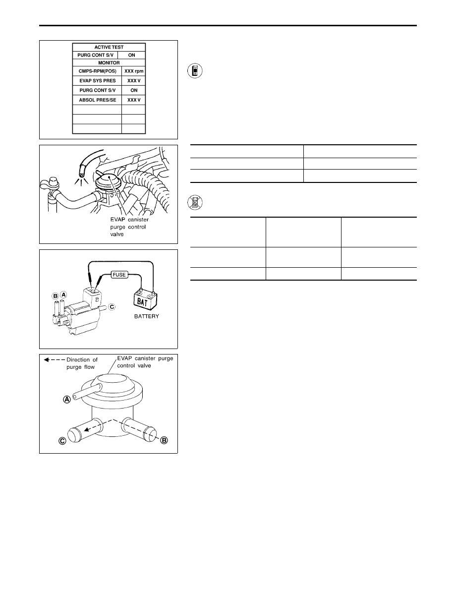
EVAP canister purge control solenoid valve
1. Turn ignition switch “ON”.
2. Select “PURG CONT S/V” of “ACTIVE TEST” mode
with CONSULT-II.
3. Start engine and warm it up to normal operating tem-
perature.
4. Disconnect vacuum hose at EVAP canister purge con-
trol valve.
5. Touch “ON” and “OFF” and check for vacuum passing
through the hose.
Condition
Vacuum
Idle
Not exist
2,000 rpm
Exist
------------------------------------------------------------------------------------------------------------------------------------------------------------------------------------------------------------------------------------------------------ OR ------------------------------------------------------------------------------------------------------------------------------------------------------------------------------------------------------------------------------------------------------
Check air passage continuity.
Condition
Air passage
continuity
between
q
A
and
q
B
Air passage
continuity
between
q
A
and
q
C
12V direct current supply
between terminals
Yes
No
No supply
No
Yes
If NG or operation takes more than 1 second, replace solenoid
valve.
SEF809W
EVAP canister purge control valve
Check EVAP canister purge control valve as follows:
1.
Blow air in port
q
A
and
q
C
, then ensure that there is no leak-
age.
2.
Blow air in port
q
B
, then ensure that there is a resistance to flow
out of port
q
C
.
3.
Apply vacuum to port
q
A
. [Approximately −13.3 to −20.0 kPa
(−100 to −150 mmHg, −3.94 to −5.91 inHg)]
Blow air in port
q
C
and ensure free flow out of port
q
B
.
TROUBLE DIAGNOSIS FOR DTC P1440
Evaporative Emission (EVAP) Control System
(Small Leak) (Positive Pressure) (Cont’d)
EC-440
Нет комментариевНе стесняйтесь поделиться с нами вашим ценным мнением.
Текст