Infiniti Q45 (FY33). Manual — part 45
20. Vehicle Does Not Decelerate By Engine
Brake
SYMPTOM:
Vehicle does not decelerate by engine brake when shifting
from 2
2
(1
2
) to 1
1
.
Is 6. Vehicle Does Not Creep Backward In
“R” Position OK?
Yes
E
No
Go to 6. Vehicle Does Not
Creep Backward In “R”
Position, AT-166.
Go to 15. Engine Speed Does Not Return
To Idle (Light Braking D
4
,
D
3
), AT-174.
SAT557IA
21. TCM Self-diagnosis Does Not Activate
(Park/Neutral Position, Overdrive Control and
Throttle Position Switch Circuit Checks)
SAT558I
SAT559I
SYMPTOM:
O/D OFF indicator lamp does not come on in TCM self-diag-
nostic procedure even the lamp circuit is good.
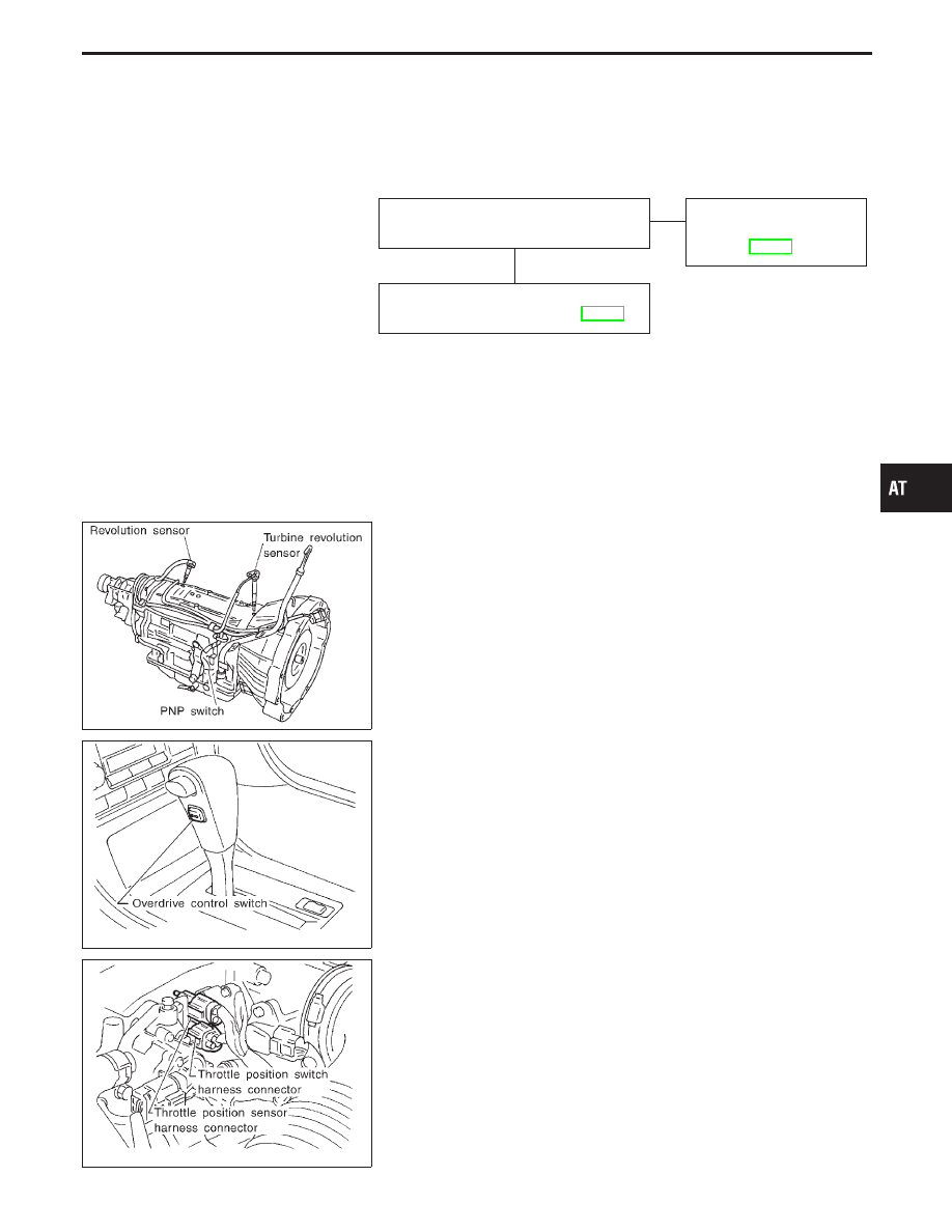
DESCRIPTION
I
PNP switch
The PNP switch assemble includes a transmission range
switch. The transmission range switch detects the selector
position and sends a signal to the TCM.
I
Overdrive control switch
Detects the overdrive control switch position (“ON” or “OFF”)
and sends a signal to the TCM.
I
Throttle position switch
Consists of a wide open throttle position switch and a closed
throttle position switch.
The wide open throttle position switch sends a signal to the
TCM when the throttle valve is open at least 1/2 of the full
throttle position. The closed throttle position switch sends a
signal to the TCM when the throttle valve is fully closed.
GI
MA
EM
LC
EC
FE
PD
FA
RA
BR
ST
RS
BT
HA
EL
IDX
TROUBLE DIAGNOSES FOR SYMPTOMS
H
AT-177

SAT737J
SAT912I
DIAGNOSTIC PROCEDURE
CHECK PARK/NEUTRAL POSITION
SWITCH CIRCUIT.
1. Turn ignition switch to “ON”
position.
(Do not start engine.)
2. Select “TCM INPUT SIGNALS”
in “DATA MONITOR”.
3. Read out “P/N”, “R”, “D”, “2” and
“1” position switches moving
selector lever to each position.
Check that the signal of the
selector lever position is indi-
cated properly.
-------------------------------------------------------------------------------------------------------------------------------------- OR --------------------------------------------------------------------------------------------------------------------------------------
1. Turn ignition switch to “ON”
position. (Do not start engine.)
2. Check voltage between TCM
terminals
q
16
,
q
17
,
q
18
,
q
19
,
q
20
and
ground while moving selector
lever through each position.
Voltage:
B: Battery voltage
0: 0V
OK
E
NG
Check the following items:
I
10A fuse [No.
18
,
located in the fuse block
(J/B)]
I
PNP switch (Refer to
“Components
Inspection”, AT-181.)
I
Harness for short or
open between ignition
switch and PNP switch
(Main harness)
I
Harness for short or
open between PNP
switch and TCM (Main
harness)
I
Ignition switch
Refer to EL section
(“POWER SUPPLY
ROUTING”).
I
Diode (P, N positions)
q
A
(Go to next page.)
Lever position
Terminal No.
q
19
q
20
q
18
q
17
q
16
P, N
B
0
0
0
0
R
0
B
0
0
0
D
0
0
B
0
0
2
0
0
0
B
0
1
0
0
0
0
B
TROUBLE DIAGNOSES FOR SYMPTOMS
21. TCM Self-diagnosis Does Not Activate
(Park/Neutral Position, Overdrive Control and
Throttle Position Switch Circuit Checks)
(Cont’d)
H
AT-178
SAT740J
SAT944IA
q
A
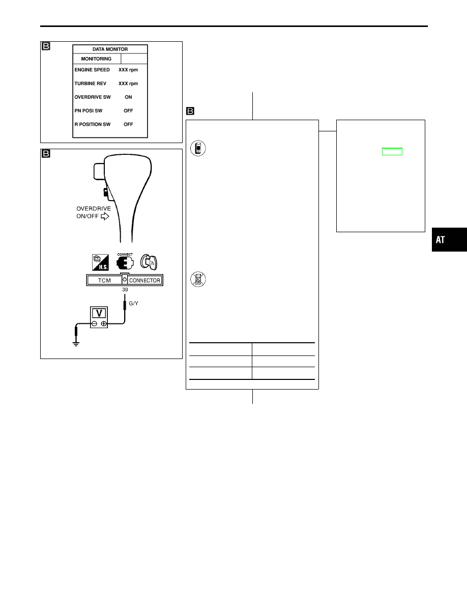
CHECK OVERDRIVE CONTROL
SWITCH CIRCUIT.
1. Turn ignition switch to “ON”
position.
(Do not start engine.)
2. Select “TCM INPUT SIGNALS”
in “DATA MONITOR” mode for
“A/T” with CONSULT-II.
3. Read out “OVERDRIVE
SWITCH”.
Check the signal of the over-
drive control switch is indicated
properly.
(Overdrive control switch “ON”
displayed on CONSULT-II
means overdrive “OFF”.)
-------------------------------------------------------------------------------------------------------------------------------------- OR --------------------------------------------------------------------------------------------------------------------------------------
1. Turn ignition switch to “ON”
position.
(Do not start engine.)
2. Check voltage between TCM
terminal
q
39
and ground when
overdrive control switch is “ON”
and “OFF”.
OK
E
NG
Check the following items:
I
Overdrive control switch
Refer to “Components
Inspection”, AT-181.
I
Harness for short or
open between TCM and
overdrive control switch
(Main harness)
I
Harness of ground circuit
for overdrive control
switch (Main harness) for
short or open
q
B
(Go to next page.)
Switch position
Voltage
ON
Battery voltage
OFF
1V or less
GI
MA
EM
LC
EC
FE
PD
FA
RA
BR
ST
RS
BT
HA
EL
IDX
TROUBLE DIAGNOSES FOR SYMPTOMS
21. TCM Self-diagnosis Does Not Activate
(Park/Neutral Position, Overdrive Control and
Throttle Position Switch Circuit Checks)
(Cont’d)
H
H
AT-179

SAT739J
SAT945IA
q
B
CHECK THROTTLE POSITION SWITCH
CIRCUIT.
1. Turn ignition switch to “ON”
position.
(Do not start engine.)
2. Select “TCM INPUT SIGNALS”
in “DATA MONITOR” mode for
“A/T” with CONSULT-II.
3. Apply vacuum to the throttle
opener. Refer to steps 1 and 2
of “Preparation”, “TCM SELF-
DIAGNOSTIC PROCEDURE
(No Tools)”, AT-49.
4. Read out “CLOSED THL/SW”
and “W/O THRL/P-SW”
depressing and releasing accel-
erator pedal.
Check the signal of throttle posi-
tion switch is indicated properly.
-------------------------------------------------------------------------------------------------------------------------------------- OR --------------------------------------------------------------------------------------------------------------------------------------
1. Turn ignition switch to “ON”
position.
(Do not start engine.)
2. Check voltage between TCM
terminals
q
14
,
q
21
and ground
while depressing, and releasing
accelerator pedal slowly. (After
warming up engine)
OK
E
NG
Check the following items:
I
10A fuse [No.
18
,
located in the fuse block
(J/B)]
I
Throttle position switch
Refer to “Components
Inspection”, AT-182.
I
Harness for short or
open between ignition
switch and throttle posi-
tion switch (Main har-
ness)
I
Harness for short or
open between throttle
position switch and TCM
(Main harness)
I
Ignition switch
Refer to EL section
(“POWER SUPPLY
ROUTING”).
Perform self-diagnosis again after driving
for a while.
OK
E
NG
1. Perform TCM input/
output signal inspection.
2. If NG, recheck TCM pin
terminals for damage or
loose connection with
harness connector.
INSPECTION END
Accelerator
pedal condi-
tion
Data monitor
CLOSED
THL/SW
W/O THRL/
P-SW
Released
ON
OFF
Fully
depressed
OFF
ON
Accelerator
pedal condi-
tion
Voltage
Terminal No.
q
14
Terminal No.
q
21
Released
Battery volt-
age
1V or less
Fully
depressed
1V or less
Battery volt-
age
TROUBLE DIAGNOSES FOR SYMPTOMS
21. TCM Self-diagnosis Does Not Activate
(Park/Neutral Position, Overdrive Control and
Throttle Position Switch Circuit Checks)
(Cont’d)
H
H
H
AT-180
Нет комментариевНе стесняйтесь поделиться с нами вашим ценным мнением.
Текст