Infiniti Q45 (FY33). Manual — part 373
SEL554W
SEL556W
SEL681UA
q
A
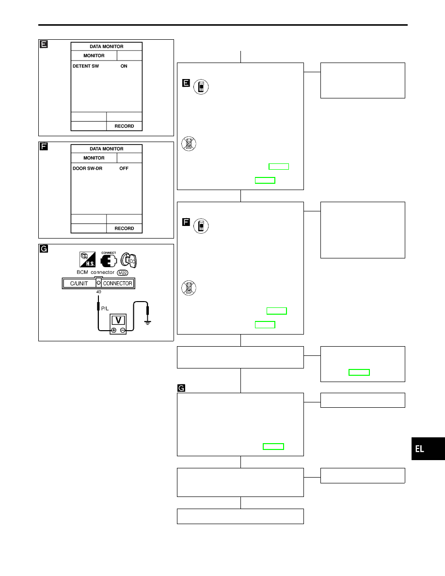
CHECK DETENTION SWITCH INPUT
SIGNAL.
CONSULT-II
See “DETENT SW” in DATA MONITOR
mode.
“DETENT SW” should be “ON” when
setting A/T selector lever in “P” posi-
tion.
-------------------------------------------------------------------------------------------------------------------------------------- OR --------------------------------------------------------------------------------------------------------------------------------------
ON BOARD
Check detention switch operation in switch
monitor (Mode II) mode.
(Refer to On board Diagnoses, EL-299.)
Refer to wiring diagram in EL-448.
OK
E
NG
Check the following.
I
Detention switch
I
Harness for open or
short
CHECK DRIVER DOOR SWITCH INPUT
SIGNAL.
CONSULT-II
See “DOOR SW DR” in DATA MONITOR
mode.
When driver’s door is open:
DOOR SW-DR
ON
When driver’s door is closed:
DOOR SW-DR
OFF
-------------------------------------------------------------------------------------------------------------------------------------- OR --------------------------------------------------------------------------------------------------------------------------------------
ON BOARD
Check driver’s door switch operation in
Switch monitor (Mode II) mode.
(Refer to On board Diagnoses EL-299.)
Refer to wiring diagram in EL-448.
OK
E
NG
Check the following.
I
Driver door switch
I
Driver door switch
ground condition
I
Harness for open or
short between driver
door switch and BCM
CHECK VEHICLE SPEED SENSOR.
Does speedometer operate normally?
Yes
E
No
Check speedometer and
vehicle speed sensor cir-
cuit.
Refer to EL-149.
CHECK VEHICLE SPEED SENSOR
PULL UP VOLTAGE.
1. Turn ignition switch to ACC.
2. Check voltage between BCM terminal
q
49
and ground.
Approx. 5V should exist.
Refer to wiring diagram in EL-448.
OK
E
NG
Replace BCM.
Check harness for open or short between
BCM terminal
q
49
and combination meter
terminal
q
16
.
OK
E
NG
Repair harness.
INSPECTION END
GI
MA
EM
LC
EC
FE
AT
PD
FA
RA
BR
ST
RS
BT
HA
IDX
AUTOMATIC DRIVE POSITIONER — IVMS
Trouble Diagnoses (Cont’d)
H
H
H
H
H
H
EL-483
SEL557W
DIAGNOSTIC PROCEDURE 20
(Seat memory switch check)
SEL067X
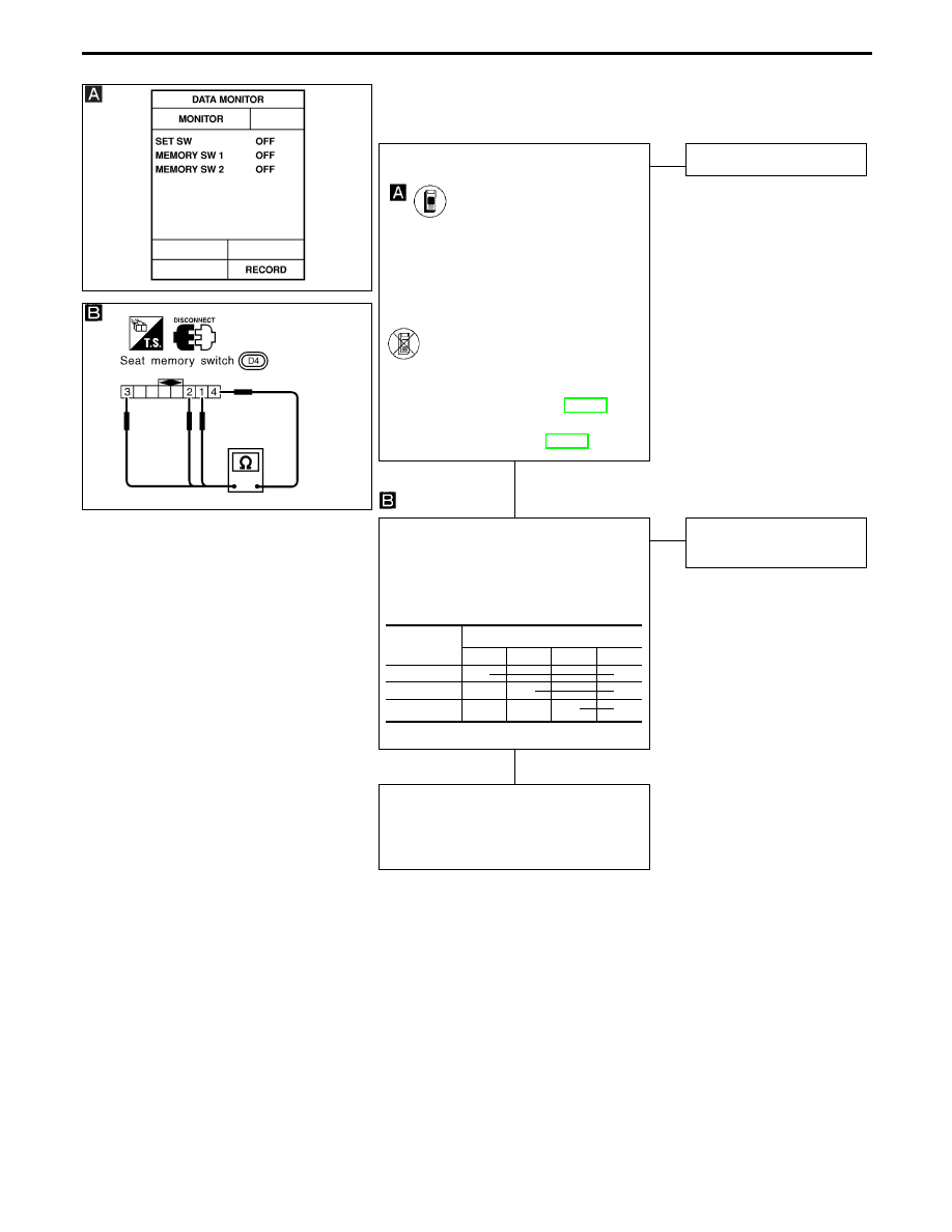
CHECK SEAT MEMORY SWITCH INPUT
SIGNAL.
CONSULT-II
See “SET SW, MEMORY SW-1, 2” in
DATA MONITOR mode.
These switches should change from
“OFF” to “ON” when switch is oper-
ated.
-------------------------------------------------------------------------------------------------------------------------------------- OR --------------------------------------------------------------------------------------------------------------------------------------
ON BOARD
Check each seat memory switch operation
in Switch monitor (Mode II) mode.
(Refer to On board diagnosis EL-299.)
Refer to wiring diagram in EL-449.
NG
E
OK
Seat memory switch is OK.
CHECK SEAT MEMORY SWITCH.
1. Disconnect seat memory switch con-
nector.
2. Check continuity between seat memory
switch terminals.
OK
E
NG
Replace seat memory
switch.
Check the following.
I
Ground circuit for seat memory switch
I
Harness for open or short between BCM
and seat memory switch
Switch
Terminals
q
1
q
2
q
3
q
4
Memory-1
q
q
Memory-2
q
q
Set
q
q
AUTOMATIC DRIVE POSITIONER — IVMS
Trouble Diagnoses (Cont’d)
H
H
EL-484
SEL558W
DIAGNOSES PROCEDURE 21
(Memory indicator check)
SEL068X
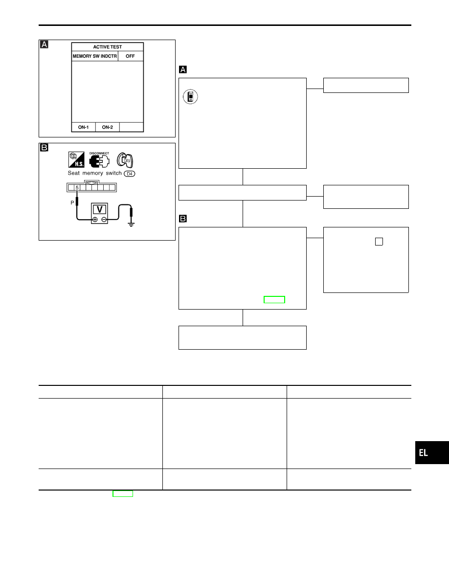
INDICATOR ACTIVE TEST
CONSULT-II
See “MEMORY SW INDCTR” in ACTIVE
TEST mode.
Perform operation shown on display.
Indicator lamp should illuminate.
Note: If CONSULT-II is not available,
skip this procedure and go to the
next procedure.
NG
E
OK
Indicator lamp is OK.
CHECK INDICATOR LAMP.
OK
E
NG
Replace seat memory
switch (indicator lamp).
CHECK POWER SUPPLY CIRCUIT FOR
INDICATOR LAMP.
1. Disconnect seat memory switch con-
nector.
2. Check voltage between seat memory
switch terminal
q
5
and ground.
Battery voltage should exist.
Refer to wiring diagram in EL-449.
OK
E
NG
Check the following.
I
7.5A fuse [No.
14
located in the fuse block
(J/B)]
I
Harness for open or
short between fuse and
indicator lamp
Check harness for open or short between
BCM and seat memory switch.
DIAGNOSTIC PROCEDURE 22
(Lumbar support check)
Symptom
Possible cause
Repair order
Power lumbar support moves neither for-
ward nor backward.
1. Power supply circuit for power lumbar
support switch
2. Ground circuit
3. Lumbar support motor
4. Lumbar support motor circuit
1. Verify battery voltage is present at ter-
minal
q
16
of power seat switch.
2. Check ground circuit for power seat
switch terminal
q
14
.
3. Check lumbar support motor.
4. Check harness for open or short
between lumbar support motor and
power seat switch.
Power lumbar support does not move for-
ward or backward.
1. Lumbar support switch
1. Check power seat switch.
Refer to wiring diagram in EL-451.
GI
MA
EM
LC
EC
FE
AT
PD
FA
RA
BR
ST
RS
BT
HA
IDX
AUTOMATIC DRIVE POSITIONER — IVMS
Trouble Diagnoses (Cont’d)
H
H
H
EL-485
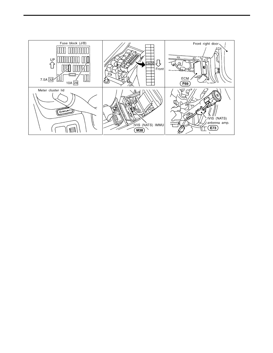
Component Parts and Harness Connector
Location
SEL950W
NOTE:
If customer reports a “No Start” condition, request ALL KEYS to be brought to the Dealer is case of
a NATS malfunction.
IVIS (Infiniti Vehicle Immobilizer System — NATS)
EL-486
Нет комментариевНе стесняйтесь поделиться с нами вашим ценным мнением.
Текст