Infiniti Q45 (FY33). Manual — part 13
Diagnostic Procedure without CONSULT-II
OBD-II SELF-DIAGNOSTIC PROCEDURE (With
GST)
Refer to EC section [“Generic Scan Tool (GST)”, “ON BOARD
DIAGNOSTIC SYSTEM DESCRIPTION”].
OBD-II SELF-DIAGNOSTIC PROCEDURE (No Tools)
Refer to EC section [“Malfunction Indicator Lamp (MIL)”, “ON
BOARD DIAGNOSTIC SYSTEM DESCRIPTION”].
SAT491J
SAT521I
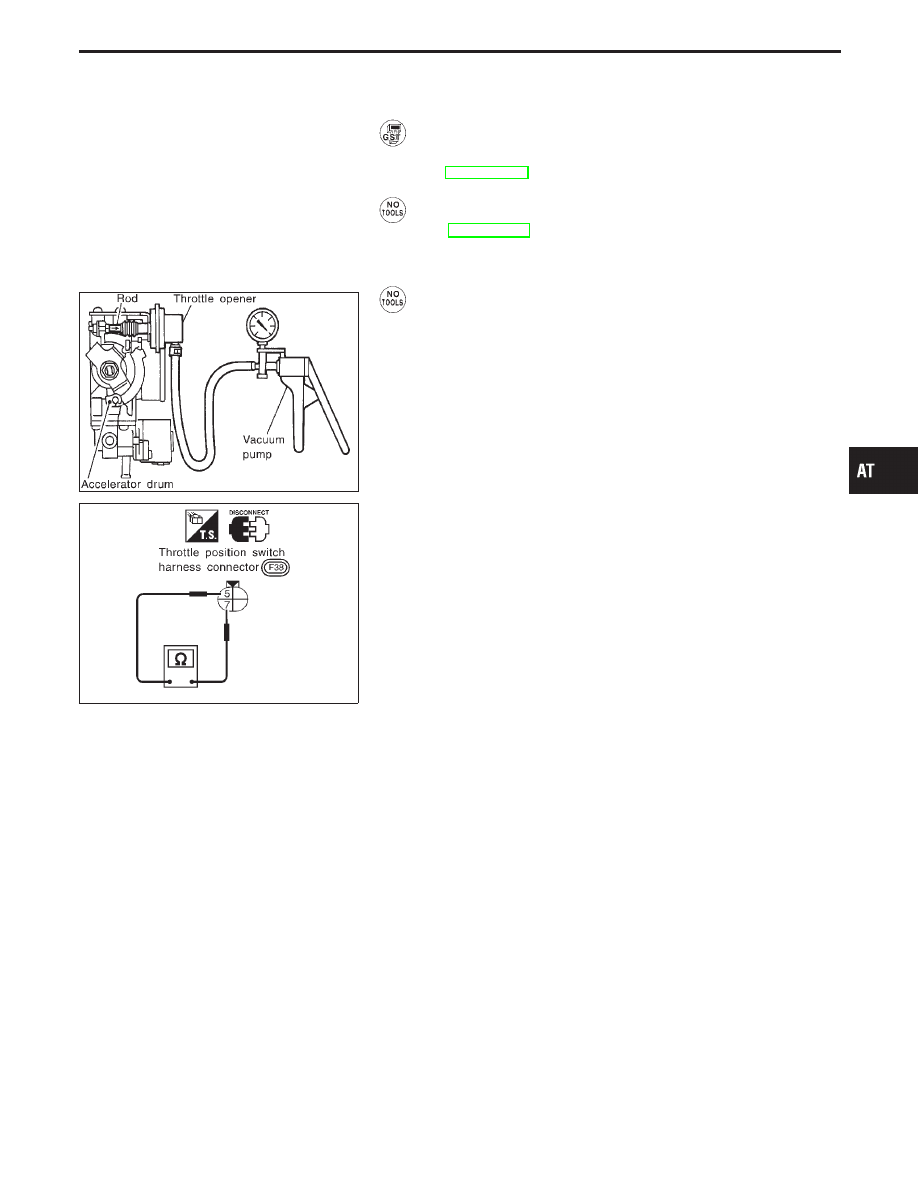
TCM SELF-DIAGNOSTIC PROCEDURE (No Tools)
Preparation
1.
Turn ignition switch to “OFF” position.
2.
Connect the handy type vacuum pump to the throttle opener
and apply vacuum −25.3 kPa (−190 mmHg, −7.48 inHg).
3.
Disconnect the throttle position switch harness connector.
4.
Turn ignition switch to “ON” position.
5.
Check continuity of the closed throttle position switch.
Continuity should exist.
(If continuity does not exist, check throttle opener and
closed throttle position switch. Then increase vacuum
until closed throttle position switch shows continuity.)
6.
Go to “DIAGNOSIS START” on next page.
GI
MA
EM
LC
EC
FE
PD
FA
RA
BR
ST
RS
BT
HA
EL
IDX
ON BOARD DIAGNOSTIC SYSTEM DESCRIPTION
AT-49
SAT967I
SAT511I
SAT968I
SAT969I
SAT970I
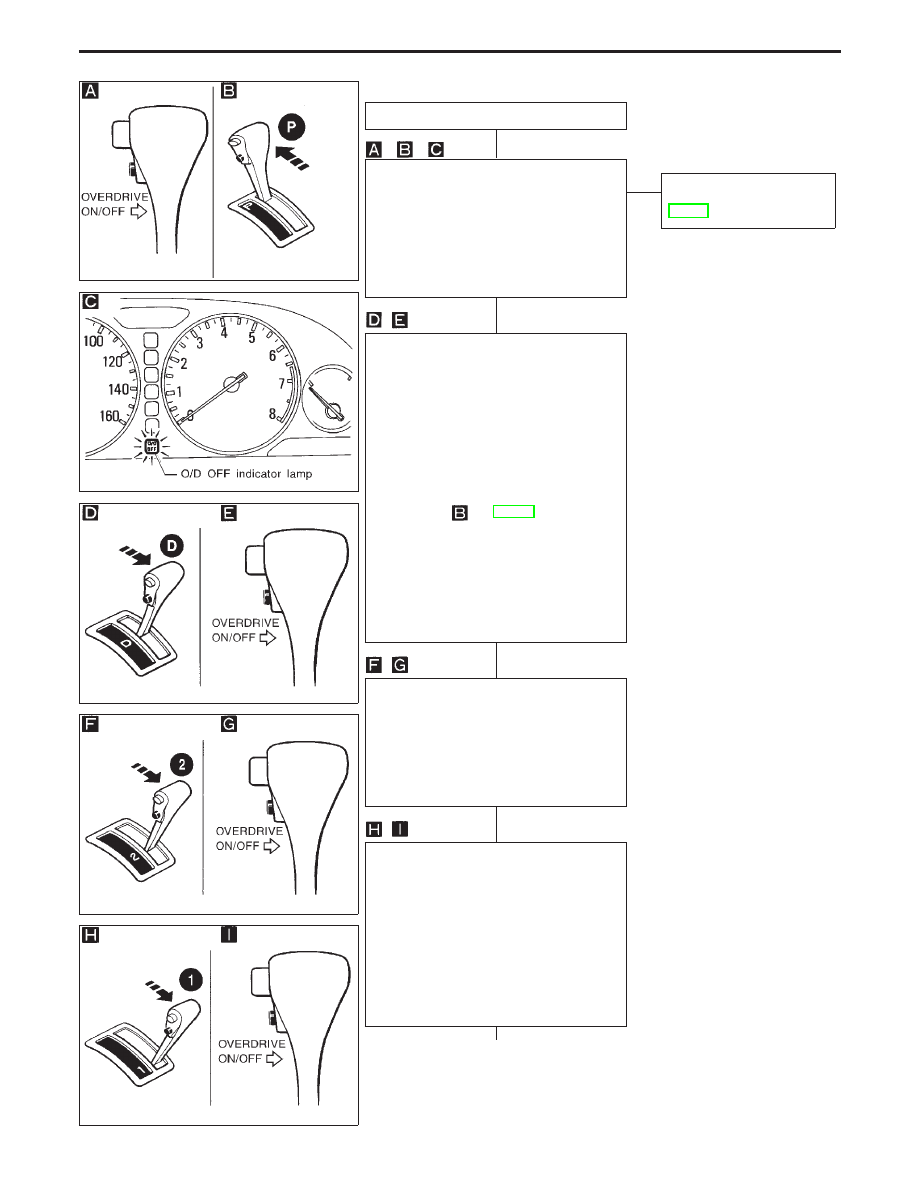
DIAGNOSIS START
1. Start the engine with selector lever in
“P” position. Warm engine to normal
operating temperature.
2. Turn ignition switch to “OFF” position.
3. Wait 5 seconds.
4. Turn ignition switch to “ON” position.
(Do not start engine.)
5. Does O/D OFF indicator lamp come on
for about 2 seconds?
Yes
E
No
Go to “1. O/D OFF Indicator
Lamp Does Not Come On”,
AT-162.
1. Turn ignition switch to “OFF” position.
2. Turn ignition switch to “ACC” position.
(“Push” shift lock release knob)
3. Move selector lever from “P” to “D”
position.
4. Turn ignition switch to “ON” position.
(Do not start engine.)
5. Depress and hold overdrive control
switch in “OFF” position (the O/D OFF
indicator lamp will be “ON”) until
directed to release the switch. (If O/D
OFF indicator lamp does not come on,
go to step
on AT-179.)
6. Turn ignition switch to “OFF” position.
7. Turn ignition switch to “ON” position (Do
not start engine.)
8. Release the overdrive control switch
(the O/D OFF indicator lamp will be
“OFF”).
9. Wait 2 seconds after ignition switch
“ON”.
1. Move selector lever to “2” position.
2. Depress and release the overdrive con-
trol switch (the O/D OFF indicator lamp
will be “ON”).
3. Depress and hold the overdrive control
switch (the O/D OFF indicator lamp will
be “OFF”) until directed to release the
switch.
1. Move selector lever to “1” position.
2. Release the overdrive control switch.
3. Depress and release the overdrive con-
trol switch (the O/D OFF indicator lamp
will be “ON”).
4. Depress and release the overdrive con-
trol switch (the O/D OFF indicator lamp
will be “OFF”).
5. Depress and hold the overdrive control
switch (the O/D OFF indicator lamp will
be “ON”) until directed to release the
switch.
q
A
ON BOARD DIAGNOSTIC SYSTEM DESCRIPTION
Diagnostic Procedure without CONSULT-II
(Cont’d)
H
H
H
H
H
AT-50
SAT981F
SAT511I
q
A
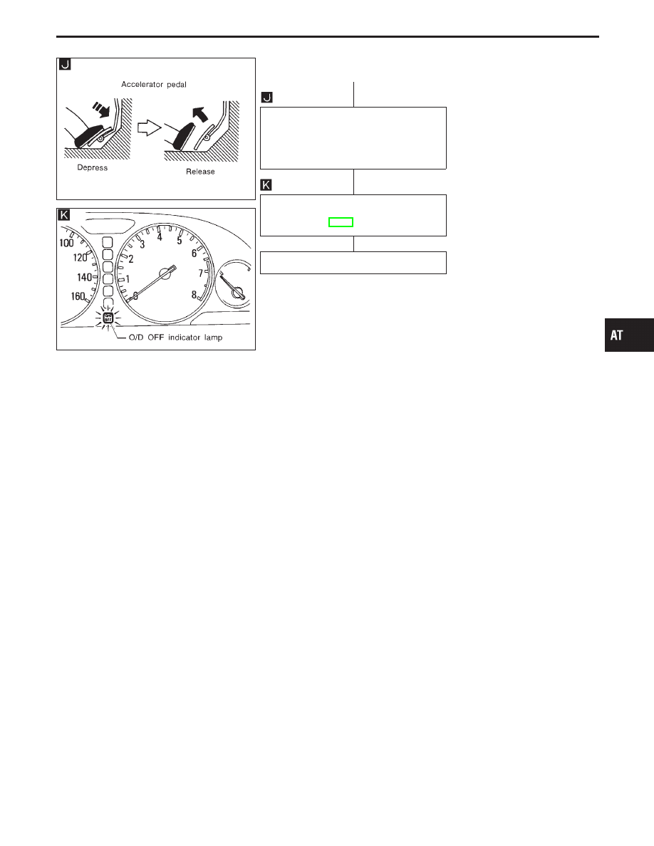
1. Depress accelerator pedal fully and
release.
2. Release the overdrive control switch
(the O/D OFF indicator lamp will begin
to flash “ON” and “OFF”).
Check O/D OFF indicator lamp.
Refer to JUDGEMENT OF SELF-DIAG-
NOSIS CODE, AT-52.
DIAGNOSIS END
GI
MA
EM
LC
EC
FE
PD
FA
RA
BR
ST
RS
BT
HA
EL
IDX
ON BOARD DIAGNOSTIC SYSTEM DESCRIPTION
Diagnostic Procedure without CONSULT-II
(Cont’d)
H
H
H
AT-51
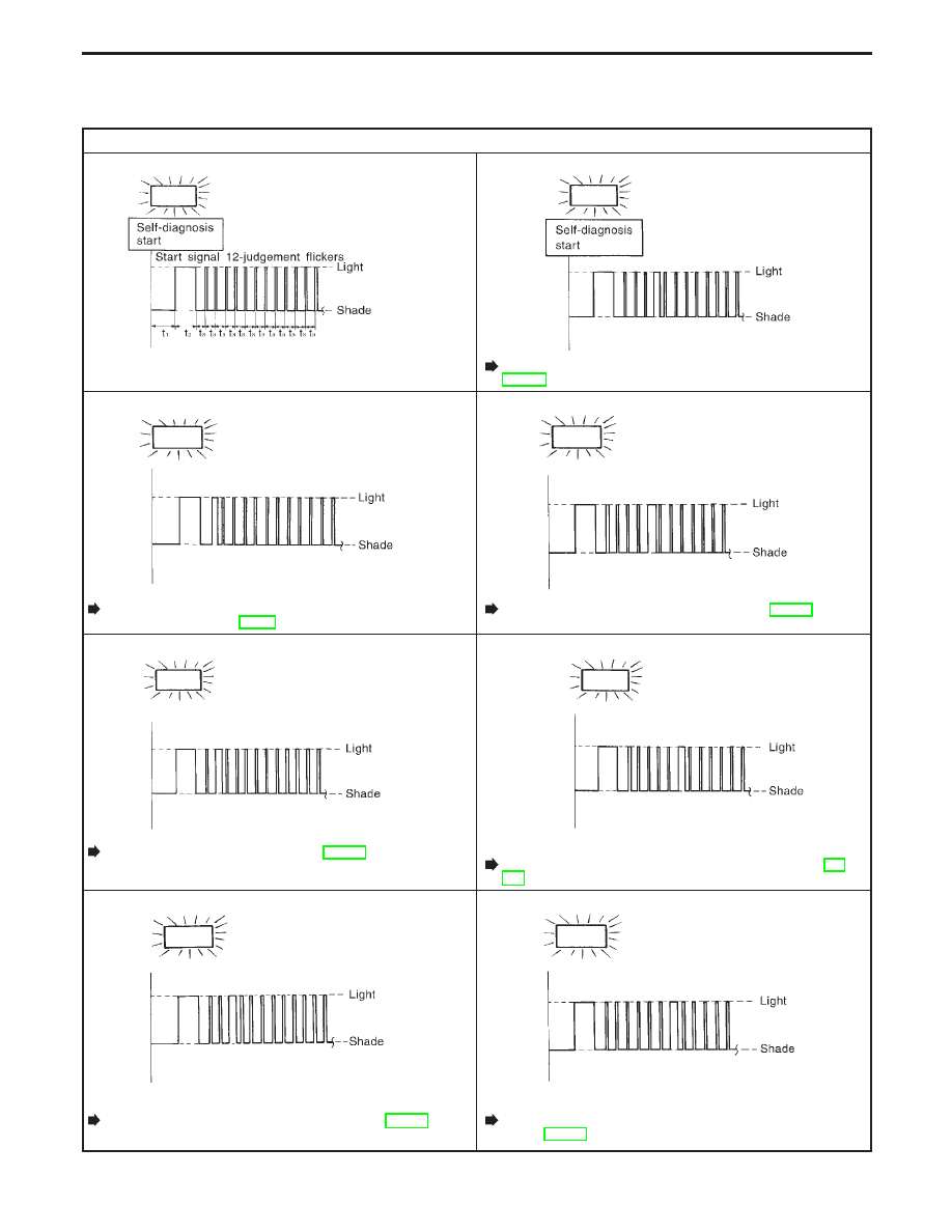
JUDGEMENT OF SELF-DIAGNOSIS CODE
O/D OFF indicator lamp
All judgement flickers are same.
SAT666I
All circuits that can be confirmed by self-diagnosis are OK.
4th judgement flicker is longer than others.
SAT670I
Shift solenoid valve A circuit is short-circuited or disconnected.
Go to Shift Solenoid Valve A (DTC: 1108),
AT-129.
1st judgement flicker is longer than others.
SAT667I
Revolution sensor circuit is short-circuited or disconnected.
Go to Vehicle Speed Sensor
⋅
A/T (Revolution
Sensor) (DTC: 1102), AT-89.
5th judgement flicker is longer than others.
SAT671I
Shift solenoid valve B circuit is short-circuited or disconnected.
Go to Shift Solenoid Valve B (DTC: 1201), AT-133.
2nd judgement flicker is longer than others.
SAT668I
Vehicle speed sensor circuit is short-circuited or disconnected.
Go to Vehicle Speed Sensor
⋅
MTR, AT-151.
6th judgement flicker is longer than others.
SAT672I
Overrun clutch solenoid valve circuit is short-circuited or
disconnected.
Go to Overrun Clutch Solenoid Valve (DTC: 1203), AT-
143.
3rd judgement flicker is longer than others.
SAT669I
Throttle position sensor circuit is short-circuited or
disconnected.
Go to Throttle Position Sensor (DTC: 1206), AT-137.
7th judgement flicker is longer than others.
SAT673I
Torque converter clutch solenoid valve circuit is short-circuited
or disconnected.
Go to Torque Converter Clutch Solenoid Valve (DTC:
1204), AT-114.
t
1
= 2.5 seconds
t
2
= 2.0 seconds
t
3
= 1.0 second
ON BOARD DIAGNOSTIC SYSTEM DESCRIPTION
Diagnostic Procedure without CONSULT-II
(Cont’d)
AT-52
Нет комментариевНе стесняйтесь поделиться с нами вашим ценным мнением.
Текст