Infiniti Q45 (FY33). Manual — part 351
SEL532W
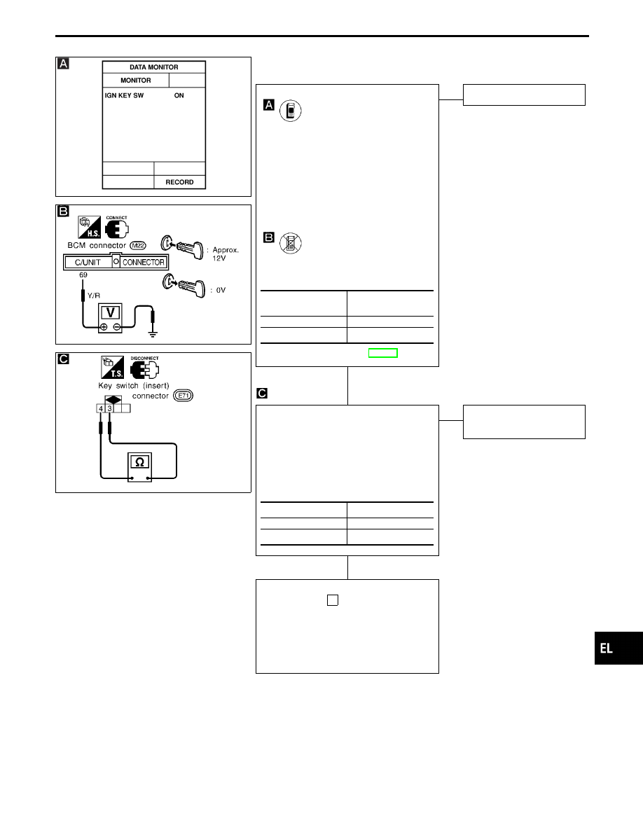
KEY SWITCH (INSERT) CHECK
SEL916V
SEL907U
CHECK KEY SWITCH INPUT SIGNAL.
CONSULT-II
See “IGN KEY SW” in DATA MONITOR
mode.
When key is inserted in ignition key cylin-
der:
IGN KEY SW
ON
When key is removed from ignition key
cylinder:
IGN KEY SW
OFF
-------------------------------------------------------------------------------------------------------------------------------------- OR --------------------------------------------------------------------------------------------------------------------------------------
TESTER
Check voltage between BCM terminals
q
69
and ground.
Refer to wiring diagram in EL-383.
NG
E
OK
Key switch is OK.
CHECK KEY SWITCH.
1. Disconnect key switch connector.
2. Check continuity between key switch
(insert) terminals
q
3
and
q
4
when key
is inserted in ignition key cylinder and
key is removed from ignition key cylin-
der.
OK
E
NG
Replace key switch
(insert).
Check the following.
I
10A fuse [No.
28
, located in fuse block
(J/B)]
I
Harness for open or short between key
switch and fuse
I
Harness for open or short between BCM
and key switch
Condition of key
switch
Voltage V
Key is inserted
Approx. 12
Key is removed
0
Condition
Continuity
Key is inserted
Yes
Key is removed
No
GI
MA
EM
LC
EC
FE
AT
PD
FA
RA
BR
ST
RS
BT
HA
IDX
INTERIOR ILLUMINATION CONTROL — IVMS
Trouble Diagnoses (Cont’d)
H
H
EL-395
SEL533W
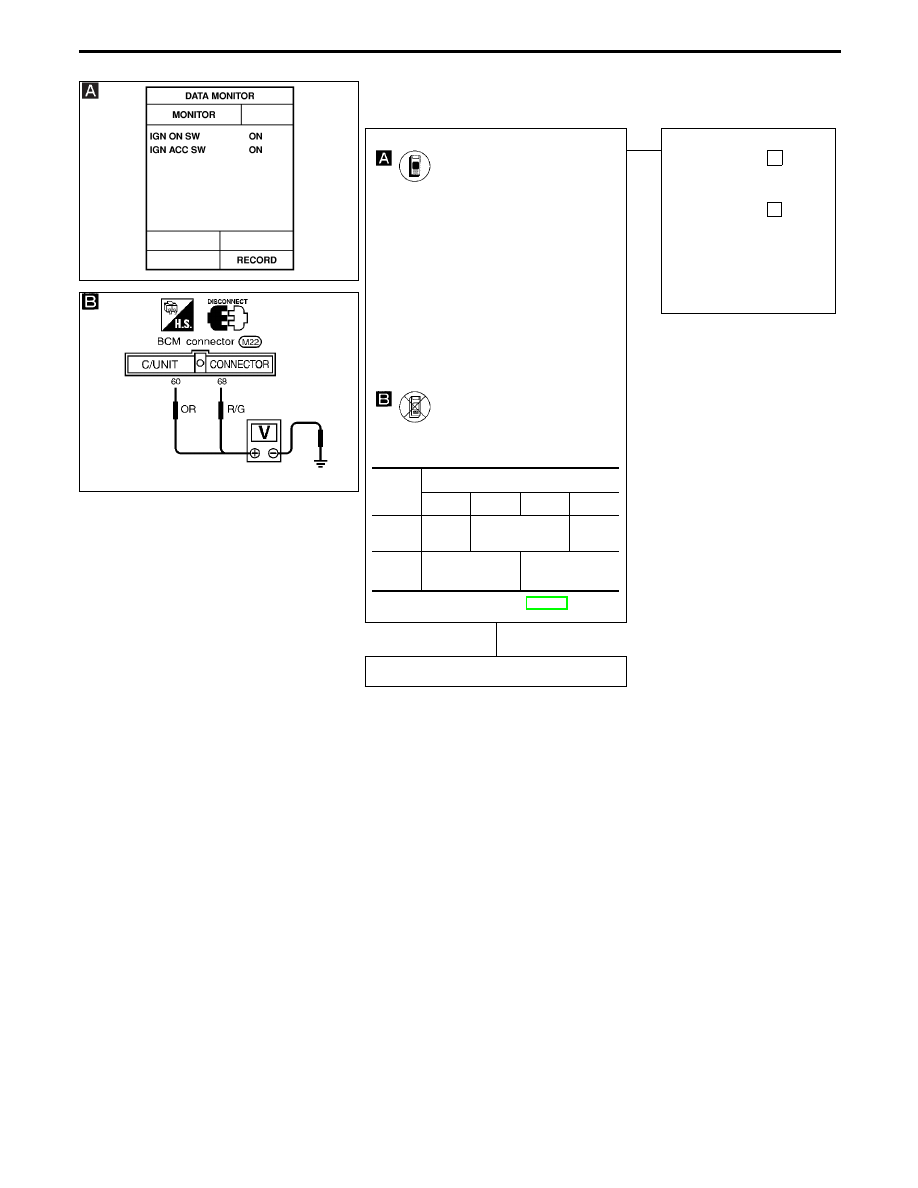
IGNITION KEY SWITCH (ACC AND IGN) INPUT SIGNAL
CHECK
SEL642UA
CHECK ACC AND IGN INPUT SIGNAL.
CONSULT-II
See “IGN ON SW” and “IGN ACC SW” in
DATA MONITOR mode.
When ignition switch is ON:
IGN ON SW
ON
IGN ACC SW
ON
When ignition switch is ACC:
IGN ON SW
OFF
IGN ACC SW
ON
When ignition switch is OFF:
IGN ON SW
OFF
IGN ACC SW
OFF
-------------------------------------------------------------------------------------------------------------------------------------- OR --------------------------------------------------------------------------------------------------------------------------------------
TESTER
Check voltage between BCM terminal
q
60
or
q
68
and ground.
Refer to wiring diagram in EL-383.
OK
E
NG
Check the following.
I
7.5A fuse [No.
23
,
located in the fuse block
(J/B)]
I
7.5A fuse [No.
32
,
located in the fuse block
(J/B)]
I
Harness for open or
short between fuse and
BCM
ACC and IGN input signal is OK.
Termi-
nals
Ignition switch position
OFF
ACC
ON
START
q
60
-
Ground
Approx.
0V
Battery voltage
Approx.
0V
q
68
-
Ground
Approx. 0V
Battery voltage
INTERIOR ILLUMINATION CONTROL — IVMS
Trouble Diagnoses (Cont’d)
H
EL-396
SEL643UA
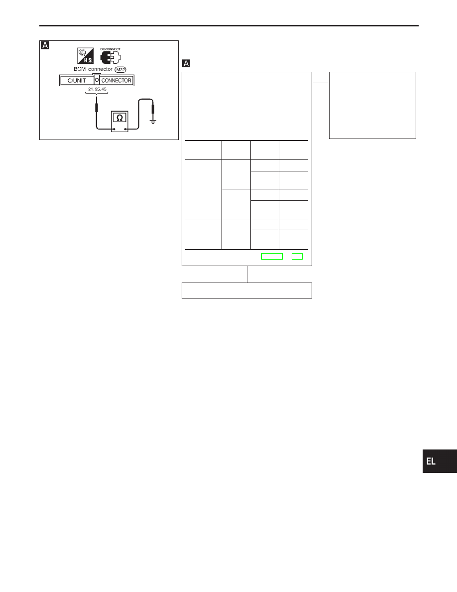
INTERIOR LAMP AND PERSONAL LAMP SWITCH
CHECK
CHECK LAMP SWITCHES INPUT SIG-
NAL.
1. Disconnect BCM connector.
2. Check continuity between BCM termi-
nals and ground.
Note: To perform this procedure, turn both
map lamp switches to OFF.
Refer to wiring diagram in EL-384 or 386.
OK
E
NG
Check the following.
I
Lamp switch
I
Lamp switch ground cir-
cuit
I
Harness for open or
short between BCM and
lamp switch
Lamp switches are OK.
Switch
Terminals Condition
Continu-
ity
Interior lamp
q
21
-
Ground
ON
Yes
AUTO/
OFF
No
q
25
-
Ground
OFF
Yes
AUTO/
ON
No
Rear per-
sonal lamp
LH/RH
q
45
-
Ground
FULL
Yes
HALF/
AUTO
No
GI
MA
EM
LC
EC
FE
AT
PD
FA
RA
BR
ST
RS
BT
HA
IDX
INTERIOR ILLUMINATION CONTROL — IVMS
Trouble Diagnoses (Cont’d)
H
EL-397
SEL534W
SEL644UA
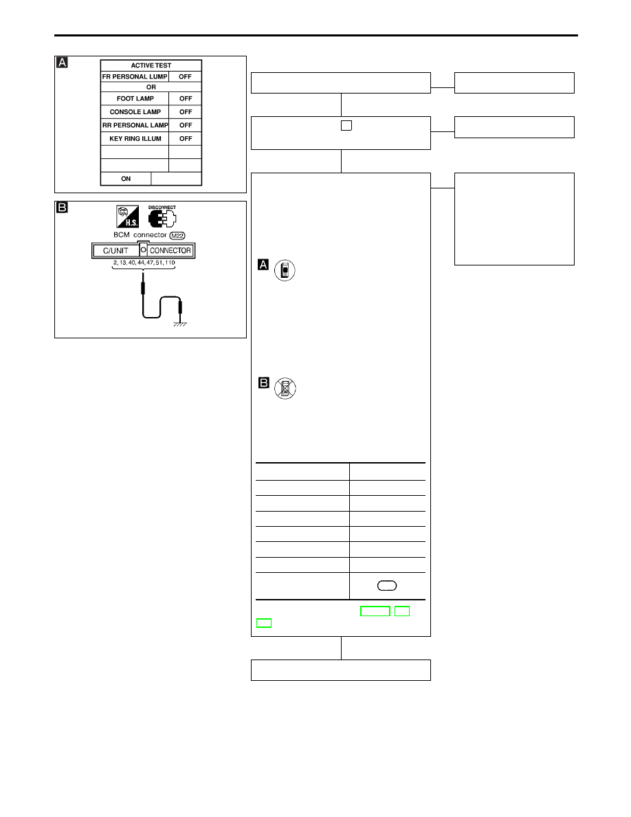
ILLUMINATION LAMP CHECK
Check illumination lamp bulb.
OK
E
NG
Replace bulb.
Check 10A fuse [No.
27
located in the
fuse block (J/B)].
OK
E
NG
Replace fuse.
CHECK ILLUMINATION LAMP OPERA-
TION.
1. Turn each lamp switch to the following
conditions.
Map lamp LH/RH switch: OFF
Interior lamp switch: AUTO
Rear personal lamp LH/RH switch: OFF
CONSULT-II
See “FR PERSONAL LAMP (Front map
lamp)”, “FOOT LAMP (Footwell lamp)”,
“CONSOLE LAMP”, “RR PERSONAL
LAMP” or “KEY RING ILLUM” in ACTIVE
TEST mode.
Perform operation shown on display.
Illumination lamp should illuminate.
-------------------------------------------------------------------------------------------------------------------------------------- OR --------------------------------------------------------------------------------------------------------------------------------------
2. Disconnect BCM connector.
3. Apply ground to each terminal of BCM
connector.
Does illumination lamp turn on?
Refer to wiring diagram in EL-384, or
386.
OK
E
NG
Check the following.
I
Harness for open or
short between fuse and
illumination lamp
I
Harness for open or
short between illumina-
tion lamp and BCM
Illumination lamps and circuit is OK.
Illumination lamp
Terminals
Console lamp
q
2
Footwell lamp
q
13
Front map lamp LH
q
40
Front map lamp RH
q
44
Rear personal lamp RH
q
47
Rear personal lamp LH
q
51
Ignition key hole illumi-
nation
110
INTERIOR ILLUMINATION CONTROL — IVMS
Trouble Diagnoses (Cont’d)
H
H
H
EL-398
Нет комментариевНе стесняйтесь поделиться с нами вашим ценным мнением.
Текст