Infiniti Q45 (FY33). Manual — part 72
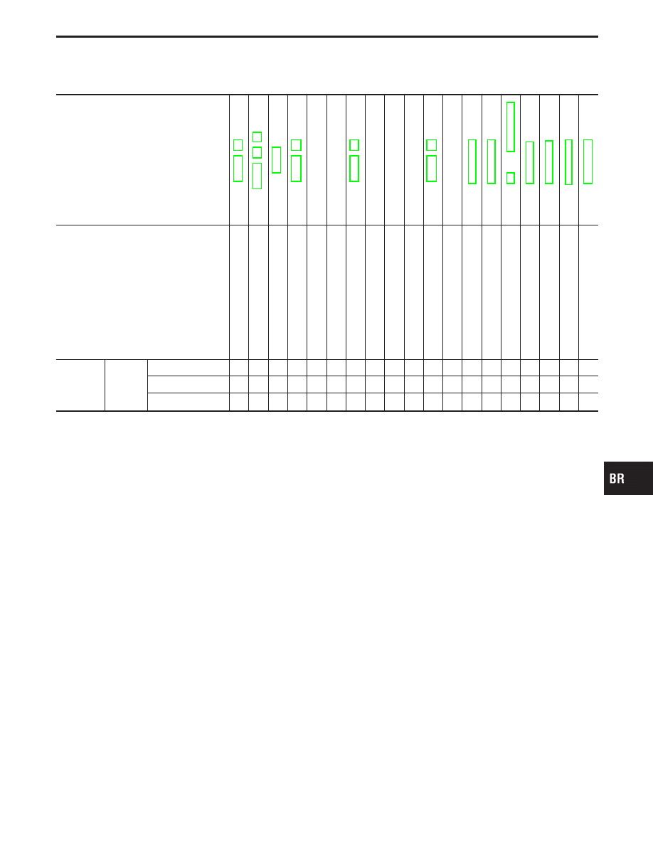
NVH Troubleshooting Chart
Use the chart below to help you find the cause of the symptom. If necessary, repair or replace these parts.
Reference page
BR-26
—
—
BR-20,
25
—
—
—
—
Refer
to
Refer
to
Refer
to
and
Refer
to
Refer
to
Refer
to
RA
section.
Refer
to
Possible cause and
SUSPECTED PARTS
Linings
or
pads
-
damaged
Linings
or
pads
-
uneven
wear
Return
spring
damaged
Shims
damaged
Rotor
or
drum
imbalance
Rotor
or
drum
damage
Rotor
or
drum
runout
Rotor
or
drum
deformation
Rotor
or
drum
deflection
Rotor
or
drum
rust
Rotor
thickness
variation
Drum
out
of
round
PROPELLER
SHAFT
DIFFERENTIAL
AXLE
AND
SUSPENSION
TIRES
ROAD
WHEEL
DRIVE
SHAFT
STEERING
Symptom
BRAKE
Noise
X
X
X
X
X
X
X
X
X
X
X
Shake
X
X
X
X
X
X
X
Shimmy, Judder
X
X
X
X
X
X
X
X
X
X
X
X
X: Applicable
GI
MA
EM
LC
EC
FE
AT
PD
FA
RA
ST
RS
BT
HA
EL
IDX
NOISE, VIBRATION AND HARSHNESS (NVH) TROUBLESHOOTING
BR-5

SBR451D
Checking Brake Fluid Level
I
Check fluid level in reservoir tank. It should be between Max.
and Min. lines on reservoir tank.
I
If fluid level is extremely low, check brake system for leaks.
I
When brake warning lamp comes on even when parking brake
lever is released, check brake system for leaks.
SBR389C
Checking Brake Line
CAUTION:
If leakage occurs around joints, retighten or, if necessary,
replace damaged parts.
1.
Check brake lines (tubes and hoses) for cracks, deterioration
or other damage. Replace any damaged parts.
2.
Check for oil leakage by fully depressing brake pedal while
engine is running.
SBR419C
Changing Brake Fluid
CAUTION:
I
Refill with new brake fluid “DOT 3”.
I
Always keep fluid level higher than minimum line on res-
ervoir tank.
I
Never reuse drained brake fluid.
I
Be careful not to splash brake fluid on painted areas; it
may cause paint damage. If brake fluid is splashed on
painted areas, wash it away with water immediately.
1.
Clean inside of reservoir tank, and refill with new brake fluid.
2.
Connect a vinyl tube to each air bleeder valve.
3.
Drain brake fluid from each air bleeder valve by depressing
brake pedal.
4.
Refill until brake fluid comes out of each air bleeder valve.
Use same procedure as in bleeding hydraulic system to refill
brake fluid. Refer to “Bleeding Brake System”, BR-7.
Brake Burnishing Procedure
Burnish the brake contact surfaces according to the following pro-
cedure after refinishing or replacing drums or rotors, after replac-
ing pads or linings, or if a soft pedal occurs at very low mileage.
CAUTION:
Only perform this procedure under safe road and traffic con-
ditions. Use extreme caution.
1.
Drive the vehicle on a straight smooth road at 50 km/h (31
MPH).
ON-VEHICLE SERVICE
BR-6

2.
Use medium brake pedal/foot effort to bring the vehicle to a
complete stop from 50 km/h (31 MPH). Adjust brake pedal/foot
pressure such that vehicle stopping time equals 3 to 5 sec-
onds.
3.
To cool the brake system, drive the vehicle at 50 km/h (31
MPH) for 1 minute without stopping.
4.
Repeat steps 1 to 3 10 times or more to complete the burnish-
ing procedure.
SBR995
Bleeding Brake System
SBR419C
CAUTION:
I
Carefully monitor brake fluid level at master cylinder dur-
ing bleeding operation.
I
If master cylinder is suspected to have air inside, bleed air
from master cylinder first. Refer to “Installation”, “MAS-
TER CYLINDER”, BR-14.
I
Fill reservoir with new brake fluid “DOT 3”. Make sure it is
full at all times while bleeding air out of system.
I
Place a container under master cylinder to avoid spillage
of brake fluid.
I
Turn ignition switch OFF and disconnect ABS actuator
connector or battery cable.
I
Bleed air in the following order:
Right rear brake
,
Left rear brake
,
Right front brake
,
Left
front brake.
1.
Connect a transparent vinyl tube to air bleeder valve.
2.
Fully depress brake pedal several times.
3.
With brake pedal depressed, open air bleeder valve to release
air.
4.
Close air bleeder valve.
5.
Release brake pedal slowly.
6.
Repeat steps 2. through 5. until clear brake fluid comes out of
air bleeder valve.
7.
Tighten air bleeder valve.
: 7 - 9 N
⋅
m (0.7 - 0.9 kg-m, 61 - 78 in-lb)
GI
MA
EM
LC
EC
FE
AT
PD
FA
RA
ST
RS
BT
HA
EL
IDX
ON-VEHICLE SERVICE
Brake Burnishing Procedure (Cont’d)
BR-7

SBR612D
SBR992
Removal
CAUTION:
I
Be careful not to splash brake fluid on painted areas; it
may cause paint damage. If brake fluid is splashed on
painted areas, wash it away with water immediately.
I
All hoses must be free from excessive bending, twisting
and pulling.
1.
Connect a vinyl tube to air bleeder valve.
2.
Drain brake fluid from each air bleeder valve by depressing
brake pedal.
3.
Remove flare nut securing brake tube to hose, then withdraw
lock spring.
4.
Cover openings to prevent entrance of dirt whenever discon-
necting hydraulic line.
Inspection
Check brake lines (tubes and hoses) for cracks, deterioration or
other damage. Replace any damaged parts.
Installation
CAUTION:
I
Refill with new brake fluid “DOT 3”.
I
Never reuse drained brake fluid.
SBR686C
1.
Tighten all flare nuts and connecting bolts.
Flare nut:
: 15 - 17 N
⋅
m (1.5 - 1.7 kg-m, 11 - 12 ft-lb)
Connecting bolt:
: 17 - 20 N
⋅
m (1.7 - 2.0 kg-m, 12 - 14 ft-lb)
2.
Refill until new brake fluid comes out of each air bleeder valve.
3.
Bleed air. Refer to “Bleeding Brake System”, BR-7.
BRAKE HYDRAULIC LINE
BR-8
Нет комментариевНе стесняйтесь поделиться с нами вашим ценным мнением.
Текст