Infiniti Q45 (FY33). Manual — part 410

ENGINE MECHANICAL
CONTENTS
PRECAUTIONS . . . . . . . . . . . . . . . ...2
Parts Requiring Angular Tightening. . . . . . . .2
Liquid Gasket Application Procedure . . . . . . ..2
PREPARATION . . . . . . . . . . . . . . . . 3
Special Service Tools . . . . . . . . . . . . ..3
Commercial Service Tools . . . . . . . . . . ...4
NOISE, VIBRATION AND HARSHNESS (NVH)
TROUBLESHOOTING . . . . . . . . . . . . . .6
NVH Troubleshooting - Engine Noise . . . . . . .7
OUTER COMPONENT PARTS . . . . . . . . . ...8
COMPRESSION PRESSURE. . . . . . . . . . 10
Measurement of Compression Pressure. . . . ...10
OIL PAN . . . . . . . . . . . . . . . . . . . 11
Removal. . . . . . . . . . . . . . . . . . 11
Installation. . . . . . . . . . . . . . . . ..12
TIMING CHAIN . . . . . . . . . . . . . . . ..13
Removal. . . . . . . . . . . . . . . . . .15
Inspection. . . . . . . . . . . . . . . . ...18
Installation. . . . . . . . . . . . . . . . ..19
OIL SEAL REPLACEMENT . . . . . . . . . . ..27
CYLINDER HEAD. . . . . . . . . . . . . . ..29
Removal. . . . . . . . . . . . . . . . . .30
Camshaft Removal . . . . . . . . . . . . . 30
Camshaft Installation . . . . . . . . . . . . .31
Cylinder Head Assembly Removal . . . . . . . 32
Disassembly. . . . . . . . . . . . . . . ...33
Inspection. . . . . . . . . . . . . . . . ...35
Assembly . . . . . . . . . . . . . . . . ...40
Installation. . . . . . . . . . . . . . . . ..40
ENGINE REMOVAL. . . . . . . . . . . . . ...43
Removal. . . . . . . . . . . . . . . . . .44
CYLINDER BLOCK . . . . . . . . . . . . . ...45
Disassembly. . . . . . . . . . . . . . . ...46
Inspection. . . . . . . . . . . . . . . . ...47
Assembly . . . . . . . . . . . . . . . . ...52
SERVICE DATA AND SPECIFICATIONS (SDS) . . ..56
General Specifications. . . . . . . . . . . ...56
Inspection and Adjustment . . . . . . . . . . 56
GI
MA
LC
EC
FE
AT
PD
FA
RA
BR
ST
RS
BT
HA
EL
IDX
Parts Requiring Angular Tightening
I
Use an angle wrench for the final tightening of the following
engine parts:
(1)
Cylinder head bolts
(2)
Main bearing cap bolts
(3)
Connecting rod cap nuts
I
Do not use a torque value for final tightening.
I
The torque value for these parts are for a preliminary step.
I
Ensure thread and seat surfaces are clean and coated with
engine oil.
SEM164F
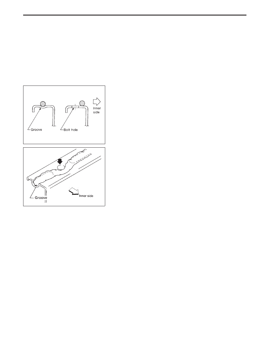
Liquid Gasket Application Procedure
a.
Use a scraper to remove all traces of old liquid gasket
from mating surfaces and grooves. Also, completely clean
any oil from these areas.
b.
Apply a continuous bead of liquid gasket to mating sur-
faces. (Use Genuine RTV silicone sealant part No. 999MP-
A7007 or equivalent.)
I
Be sure liquid gasket diameter is as specified.
AEM080
c.
Apply liquid gasket around the inner side of bolt holes
(unless otherwise specified).
d.
Assembly should be done within 5 minutes after coating.
e.
Wait at least 30 minutes before refilling engine oil and
engine coolant.
PRECAUTIONS
EM-2
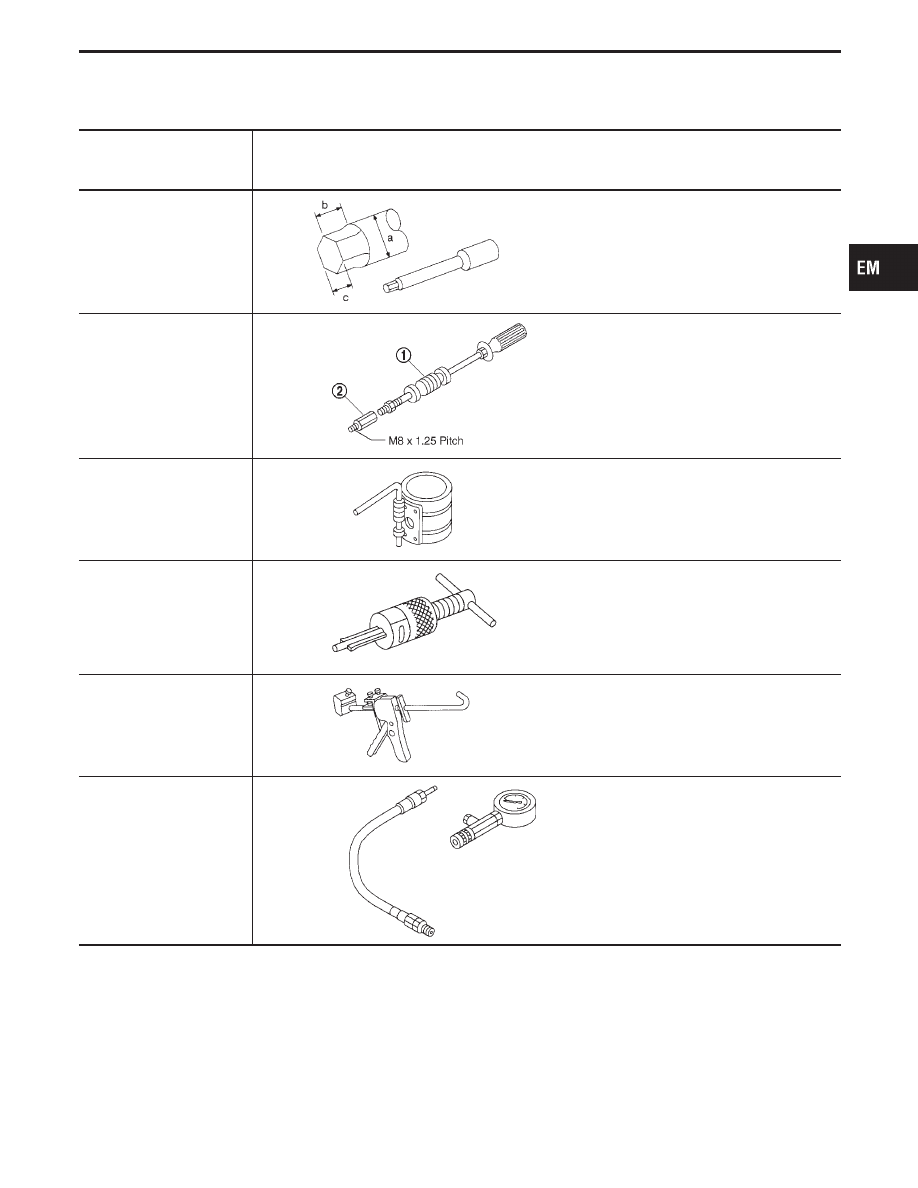
Special Service Tools
The actual shapes of Kent-Moore tools may differ from those of special service tools illustrated here.
Tool number
(Kent-Moore No.)
Tool name
Description
ST10120000
(J24239-01)
Cylinder head bolt wrench
NT583
Loosening and tightening cylinder head bolt
a: 13 mm (0.51 in) dia.
b: 12 mm (0.47 in)
c: 10 mm (0.39 in)
q
1
(J6125-1B)
Slide hammer
q
2
(J38139-1)
Slide hammer adapter
NT377
Removing main bearing cap
EM03470000
(J8037)
Piston ring compressor
NT044
Installing piston assembly into cylinder bore
ST16610001
(J23907)
Pilot bushing puller
NT045
Removing crankshaft pilot bushing
WS39930000
(
—
)
Tube presser
NT052
Pressing the tube of liquid gasket
EG15060000
(
—
)
Compression gauge and
adapter
NT238
GI
MA
LC
EC
FE
AT
PD
FA
RA
BR
ST
RS
BT
HA
EL
IDX
PREPARATION
EM-3
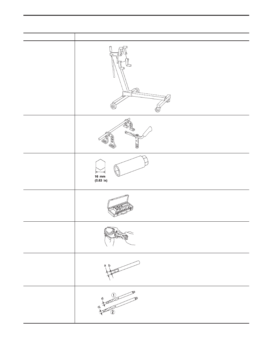
Commercial Service Tools
Tool name
Description
Engine stand assembly
NT388
Disassembling and assembling
Valve spring compressor
NT103
Disassembling and assembling valve com-
ponents
Spark plug wrench
NT047
Removing and installing spark plug
Valve seat cutter set
NT048
Finishing valve seat dimensions
Piston ring expander
NT030
Removing and installing piston ring
Valve guide drift
NT015
Removing and installing valve guide
Intake:
a = 11.5 mm (0.453 in) dia.
b = 6.5 mm (0.256 in) dia.
Exhaust:
a = 12.5 mm (0.492 in) dia.
b = 7.5 mm (0.295 in) dia.
Valve guide reamer
NT016
Reaming valve guide
q
1
or hole for over-
size valve guide
q
2
Intake:
d
1
= 7.000 mm (0.2756 in) dia.
Exhaust:
d
1
= 8.000 mm (0.3150 in) dia.
Intake:
d
2
= 11.175 mm (0.4400 in) dia.
Exhaust:
d
2
= 12.175 mm (0.4793 in) dia.
PREPARATION
EM-4
Нет комментариевНе стесняйтесь поделиться с нами вашим ценным мнением.
Текст