Infiniti Q45 (FY33). Manual — part 284
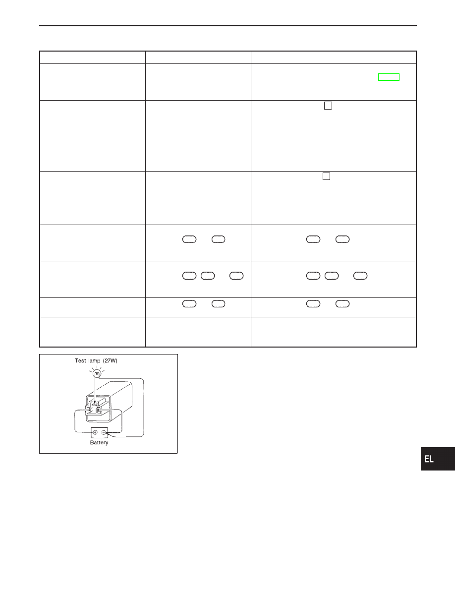
Trouble Diagnoses
Symptom
Possible cause
Repair order
Turn signal and hazard warning
lamps do not operate.
1. Hazard switch
2. Combination flasher unit
3. Open in combination flasher unit
circuit
1. Check hazard switch.
2. Refer to combination flasher unit check. (EL-127)
3. Check wiring to combination flasher unit for open cir-
cuit.
Turn signal lamps do not operate
but hazard warning lamps operate.
1. 7.5A fuse
2. Hazard switch
3. Turn signal switch
4. Open in turn signal switch circuit
1. Check 7.5A fuse [No.
19
, located in the fuse block
(J/B)]. Turn ignition switch ON and verify battery
positive voltage is present at terminal
q
2
of hazard
switch.
2. Check hazard switch.
3. Check turn signal switch.
4. Check L/B wire between combination flasher unit and
turn signal switch for open circuit.
Hazard warning lamps do not oper-
ate but turn signal lamps operate.
1. 10A fuse
2. Hazard switch
3. Open in hazard switch circuit
1. Check 10A fuse [No.
13
, located in the fuse block
(J/B)]. Verify battery positive voltage is present at
terminal
q
3
of hazard switch.
2. Check hazard switch.
3. Check L/B wire between combination flasher unit and
hazard switch for open circuit.
Front turn signal lamp LH or RH
does not operate.
1. Bulb
2. Grounds
E22
and
E36
3. Open in front turn signal lamp
LH or RH circuit
1. Check bulb.
2. Check grounds
E22
and
E36
.
3. Check wire between fuse block and front turn signal
lamp LH or RH for open circuit.
Rear turn signal lamp LH or RH
does not operate.
1. Bulb
2. Grounds
T12
,
B22
and
B35
3. Open in rear turn signal lamp
LH or RH circuit
1. Check bulb.
2. Check grounds
T12
,
B22
and
B35
.
3. Check wire between fuse block and rear turn signal
lamp LH or RH for open circuit.
LH and RH turn indicators do not
operate.
1. Grounds
M14
and
M47
1. Check grounds
M14
and
M47
.
LH or RH turn indicator does not
operate.
1. Bulb
2. Open in turn indicator circuit
1. Check bulb in combination meter.
2. Check wire between hazard switch and combination
meter (turn indicator) for open circuit.
SEL122E
Electrical Components Inspection
COMBINATION FLASHER UNIT CHECK
I
Before checking, ensure that bulbs meet specifications.
I
Connect a battery and test lamp to the combination flasher
unit, as shown. Combination flasher unit is properly function-
ing if it blinks when power is supplied to the circuit.
GI
MA
EM
LC
EC
FE
AT
PD
FA
RA
BR
ST
RS
BT
HA
IDX
TURN SIGNAL AND HAZARD WARNING LAMPS
EL-127

System Description
Power is supplied at all times
I
through 15A fuse (No.
63
, located in the fuse, fusible link and relay box)
I
to tail lamp relay terminals
q
1
and
q
6
.
Ground is supplied to tail lamp relay terminal
q
2
, when the lighting switch is moved to the 1ST or 2ND posi-
tion. The tail lamp relay is energized.
The lighting switch must be in the 1ST or 2ND position for illumination.
The illumination control switch that controls the amount of current to the illumination system. As the amount
of current increases, the illumination becomes brighter.
The following chart shows the power and ground connector terminals for the components included in the illu-
mination system.
Component
Connector No.
Power terminal
Ground terminal
Combination meter
N12
,
N14
q
16
,
q
41
q
17
,
q
38
Rear cigarette lighter
D45
,
D65
q
3
— (Unit ground)
Rear ashtray
D44
,
D64
q
1
q
2
Glove box lamp
M26
q
1
q
2
TCS switch
N7
q
5
q
6
Active damper suspension select switch
N5
q
7
q
8
Audio unit
N20
q
8
q
7
Display and NAVI control unit (With naviga-
tion system)
N32
,
N33
q
8
q
24
Illumination time control switch
N8
q
2
q
4
Front cigarette lighter
N6
q
2
— (Unit ground)
Headlamp aiming switch
N4
q
3
q
4
A/T device
M36
q
3
q
4
Front power window main switch
D12
q
2
q
1
Auto anti-dazzling inside mirror
R4
q
3
q
4
IVCS switch
R10
q
2
q
12
Driver’s door control unit
D13
q
9
q
2
Passenger door control unit
D29
q
9
q
2
Clock (Without navigation system)
N28
q
3
q
2
A/C control unit (Without navigation system)
N17
q
1
q
4
Hazard switch
N22
q
7
q
8
Telephone switch
N25
q
24
q
23
Rear sunshade switch
N30
q
4
q
5
Illumination control switch
N23
q
1
q
5
The ground for all of the components except for rear ashtray, and rear cigarette lighter, glove box lamp and
front cigarette lighter are controlled through terminals
q
4
and
q
5
of the illumination control switch and body
grounds
M14
and
M47
.
ILLUMINATION
EL-128
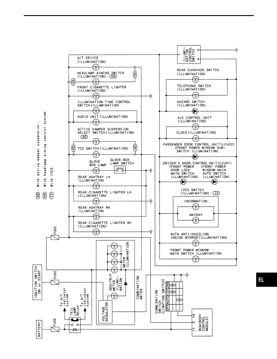
Schematic
WITHOUT NAVIGATION SYSTEM
TEL350M
GI
MA
EM
LC
EC
FE
AT
PD
FA
RA
BR
ST
RS
BT
HA
IDX
ILLUMINATION
EL-129

WITH NAVIGATION SYSTEM
TEL351M
ILLUMINATION
Schematic (Cont’d)
EL-130
Нет комментариевНе стесняйтесь поделиться с нами вашим ценным мнением.
Текст