Infiniti Q45 (FY33). Manual — part 301
SEL506W
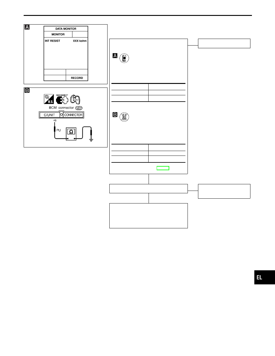
DIAGNOSTIC PROCEDURE 2
SYMPTOM: Intermittent time of wiper cannot be adjusted.
SEL566UA
CHECK INTERMITTENT WIPER VOL-
UME INPUT SIGNAL.
CONSULT-II
See “INT RESIST” in DATA MONITOR
mode while turning intermittent wiper vol-
ume.
-------------------------------------------------------------------------------------------------------------------------------------- OR --------------------------------------------------------------------------------------------------------------------------------------
TESTER
Measure resistance between BCM termi-
nal
q
48
and ground while turning intermit-
tent wiper volume.
Refer to wiring diagram in EL-187.
NG
E
OK
Replace BCM.
Check front wiper switch.
OK
E
NG
Replace intermittent wiper
volume.
Check the following.
I
Harness for open or short between BCM
and intermittent wiper volume
I
Intermittent wiper volume ground circuit
Position of wiper knob
Resistance k
Ω
Short interval
Approx. 0
Long interval
Approx. 1
Position of wiper knob
Resistance k
Ω
Short interval
Approx. 0
Long interval
Approx. 1
GI
MA
EM
LC
EC
FE
AT
PD
FA
RA
BR
ST
RS
BT
HA
IDX
WIPER AND WASHER
Trouble Diagnoses (Cont’d)
H
H
EL-195
SEL507W
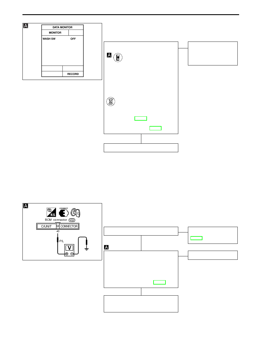
DIAGNOSTIC PROCEDURE 3
SYMPTOM: Wiper and washer activate individually but not in
combination.
CHECK WASHER SWITCH INPUT SIG-
NAL.
CONSULT-II
See “WASH SW” in DATA MONITOR
mode.
When washer switch is ON:
WASH SW
ON
When washer switch is OFF:
WASH SW
OFF
-------------------------------------------------------------------------------------------------------------------------------------- OR --------------------------------------------------------------------------------------------------------------------------------------
ON BOARD
Check wiper switch (WASH) in Switch
monitor (Mode II) mode. (Refer to On
board Diagnosis, EL-299).
Refer to wiring diagram in EL-187.
OK
E
NG
Check the following.
I
Harness for open or
short between BCM and
wiper switch
Replace BCM.
SEL681UA
DIAGNOSTIC PROCEDURE 4
SYMPTOM: Intermittent wiper operates, but there is no change
in intermittent time between when vehicle is
stopped and moving.
Does speedometer operate normally?
Yes
E
No
Check vehicle speed sen-
sor circuit. Refer to
EL-151.
CHECK VEHICLE SPEED SENSOR
PULL UP VOLTAGE.
1. Turn ignition switch to ACC.
2. Check voltage between BCM terminal
q
49
and ground.
Approx. 5V should exist.
Refer to wiring diagram in EL-188.
OK
E
NG
Replace BCM.
Check harness for open or short between
BCM terminal
q
49
and combination meter
terminal
q
18
.
WIPER AND WASHER
Trouble Diagnoses (Cont’d)
H
H
H
EL-196
SEL925U
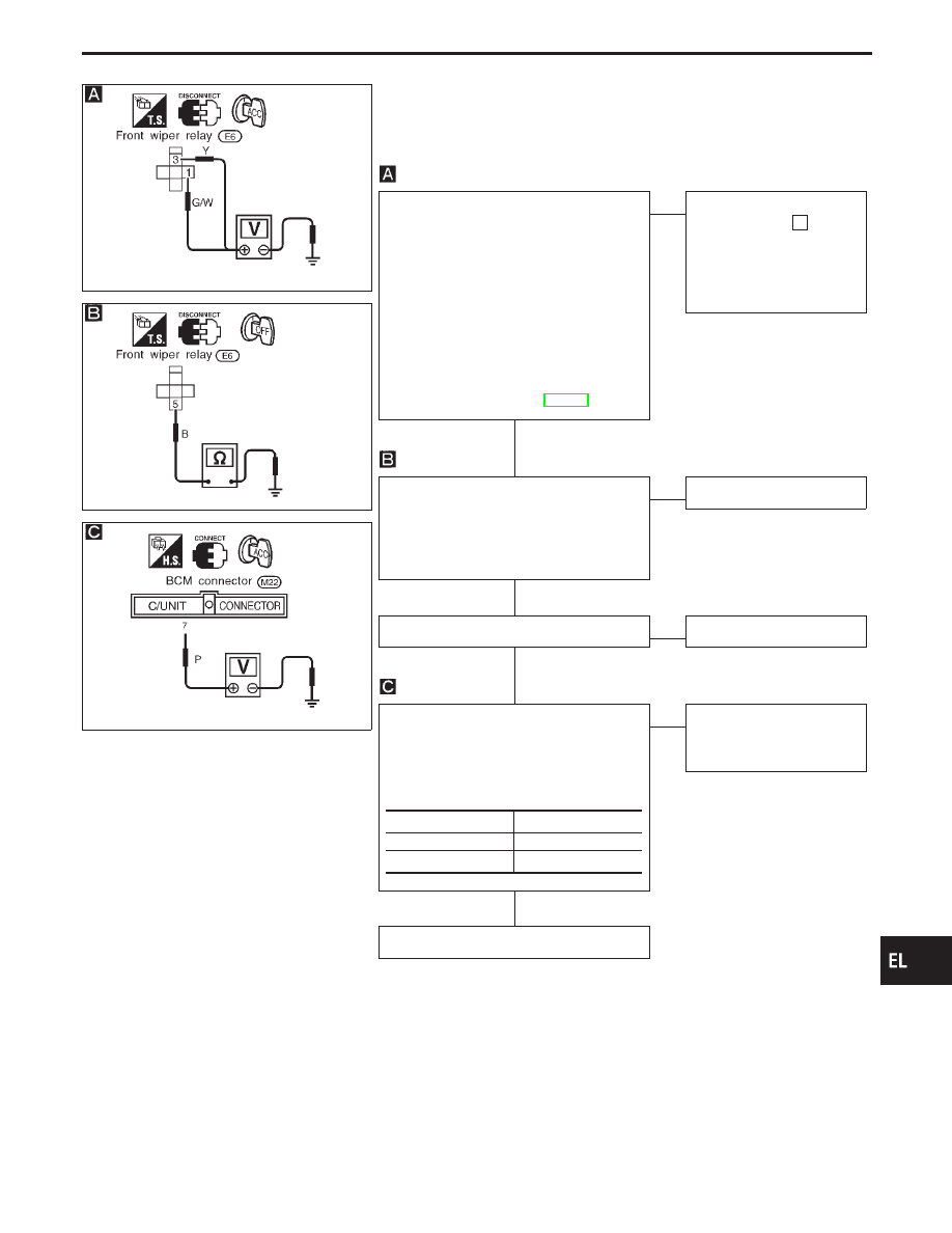
DIAGNOSTIC PROCEDURE 5
SYMPTOM: Wiper and washer activate individually but inter-
mittent wiper and washer combination does not
operate.
SEL926U
SEL565UA
CHECK POWER SUPPLY CIRCUIT FOR
FRONT WIPER RELAY.
1. Disconnect front wiper relay.
2. Turn wiper switch to OFF or INT posi-
tion.
3. Turn ignition switch to ACC position.
4. Check voltage between front wiper
relay connector terminal
q
1
or
q
3
and
ground.
Battery voltage should exist.
Refer to wiring diagram in EL-186.
OK
E
NG
Check the following.
I
20A fuse [No.
11
,
located in the fuse block
(J/B)]
I
Harness for open or
short
CHECK GROUND CIRCUIT FOR FRONT
WIPER RELAY.
Check continuity between front wiper con-
nector terminal
q
5
and ground.
Continuity should exist.
OK
E
NG
Repair harness.
Check front wiper relay.
OK
E
NG
Replace relay.
CHECK BCM OUTPUT SIGNAL.
1. Connect front wiper relay.
2. Turn ignition switch to ACC.
3. Check voltage between BCM connector
terminal
q
7
and ground.
NG
E
OK
Check harness for open or
short between front wiper
relay and BCM.
Replace BCM.
Wiper switch condition
Voltage V
Wash
0 (for 0.7 sec.)
OFF
Approx. 12
GI
MA
EM
LC
EC
FE
AT
PD
FA
RA
BR
ST
RS
BT
HA
IDX
WIPER AND WASHER
Trouble Diagnoses (Cont’d)
H
H
H
H
EL-197
SEL543TA
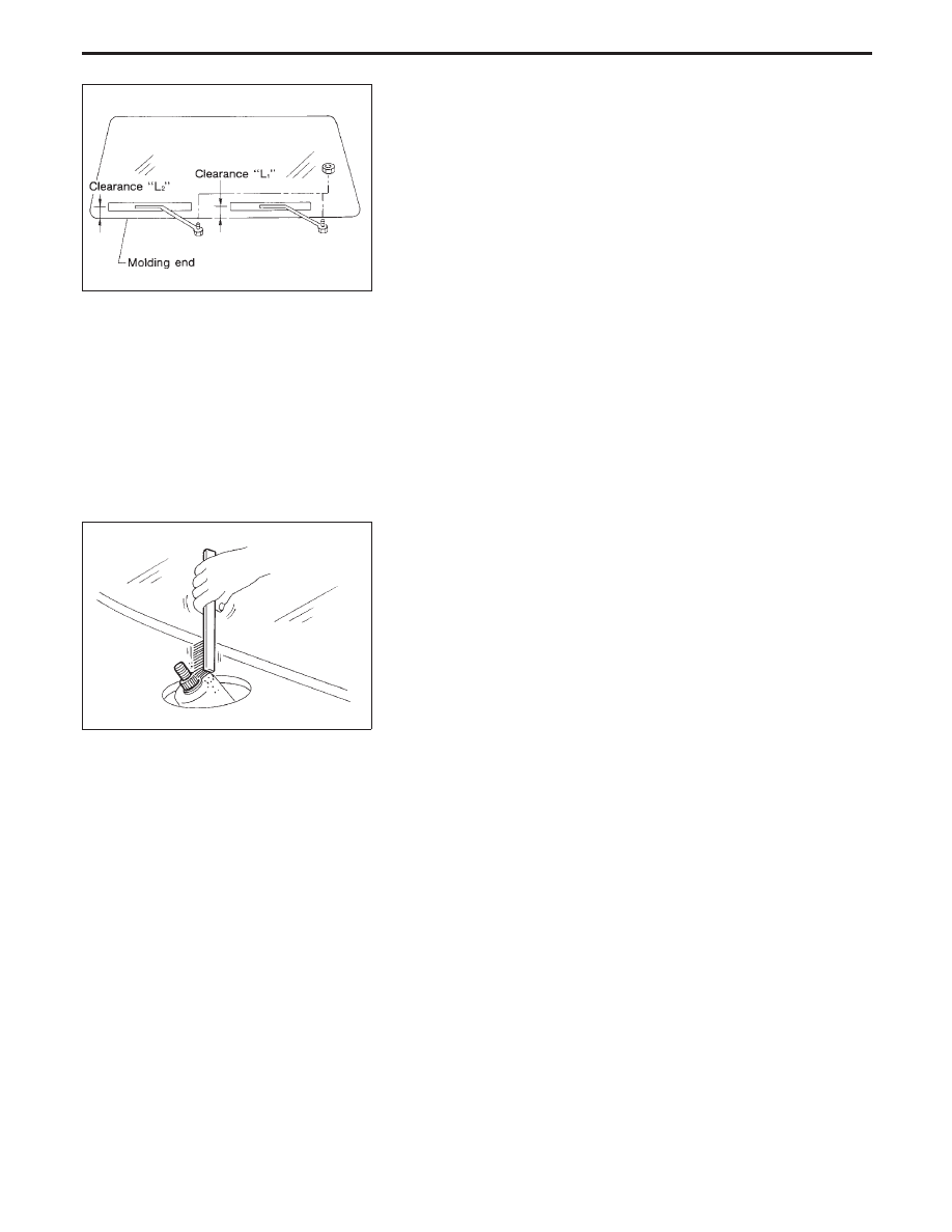
Removal and Installation
WIPER ARMS
1.
Prior to wiper arm installation, turn on wiper switch to operate
wiper motor and then turn it “OFF” (Auto Stop).
2.
Lift the blade up and then set it down onto glass surface to set
the blade center to clearance “L
1
” & “L
2
” immediately before
tightening nut.
3.
Eject washer fluid. Turn on wiper switch to operate wiper motor
and then turn it “OFF”.
4.
Ensure that wiper blades stop within clearance “L
1
” & “L
2
”.
Clearance “L
1
”: 20 - 34 mm (0.79 - 1.34 in)
Clearance “L
2
”: 23 - 37 mm (0.91 - 1.46 in)
I
Tighten wiper arm nuts to specified torque.
Front wiper: 21 - 26 N
⋅
m (2.1 - 2.7 kg-m, 15 - 20 ft-lb)
SEL024J
I
Before reinstalling wiper arm, clean up the pivot area as
illustrated. This will reduce possibility of wiper arm loose-
ness.
WIPER AND WASHER
EL-198
Нет комментариевНе стесняйтесь поделиться с нами вашим ценным мнением.
Текст