Infiniti Q45 (FY33). Manual — part 417
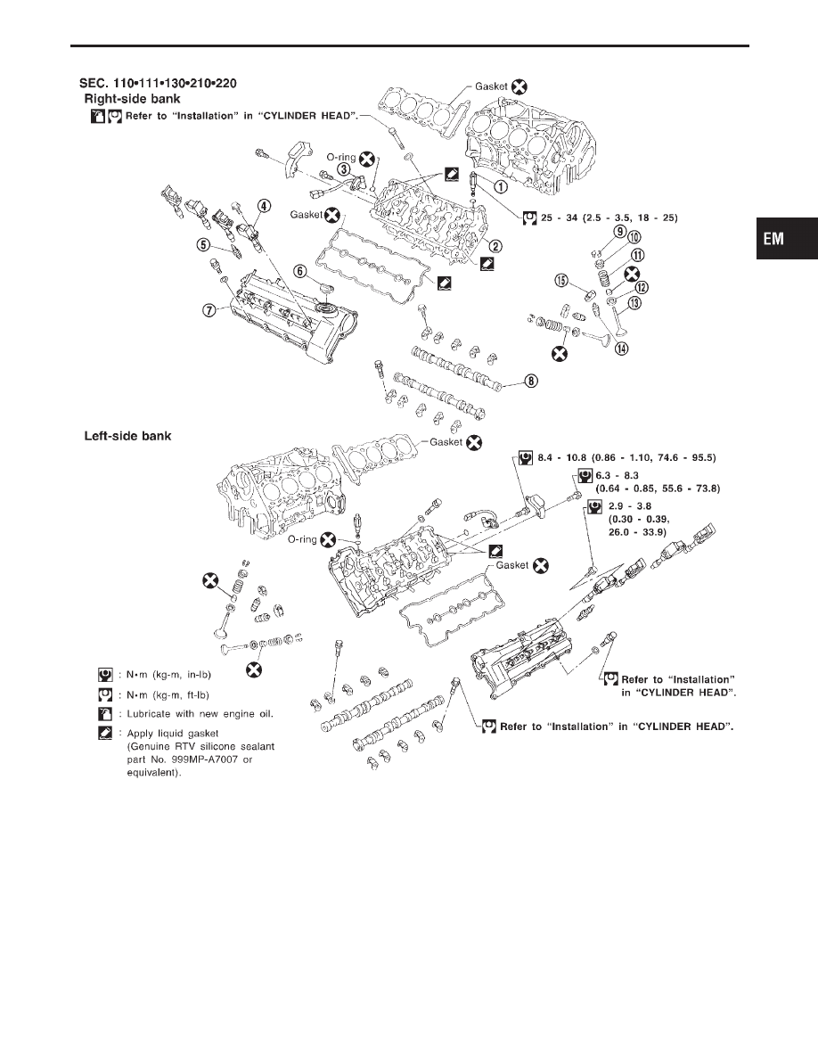
SEM444FB
q
1
Intake valve timing control sole-
noid valve
q
2
Cylinder head
q
3
Intake valve timing control position
sensor
q
4
Ignition coil with power transistor
q
5
Spark plug
q
6
Oil filler cap
q
7
Rocker cover
q
8
Camshaft
q
9
Valve collet
q
10
Valve spring retainer
q
11
Valve spring
q
12
Valve spring seat
q
13
Valve
q
14
Hydraulic lash adjuster
q
15
Roller rocker arm
GI
MA
LC
EC
FE
AT
PD
FA
RA
BR
ST
RS
BT
HA
EL
IDX
CYLINDER HEAD
EM-29
CAUTION:
I
When installing camshafts, chain tensioners, oil seals, or
other sliding parts, lubricate contacting surfaces with new
engine oil.
I
Apply new engine oil to threads and seat surfaces when
installing cylinder head, camshaft sprocket, crankshaft
pulley, and camshaft bracket.
Removal
Note:
The cylinder head assembly removal and installation should
be performed after removing the engine assembly. This sec-
tion describes the removal of the camshaft, rocker arms and
hydraulic lash adjusters.
Camshaft Removal
I
Release fuel pressure. Refer to “Fuel Pressure Release”,
“BASIC SERVICE PROCEDURE” in EC section.
I
Remove ornament cover.
I
Remove under cover.
I
Remove radiator.
I
Remove cooling fan.
I
Remove water inlet and outlet.
I
Remove alternator belt.
I
Remove alternator belt idler bracket.
I
Remove air duct.
I
Remove intake manifold collector.
I
Remove intake valve timing control solenoid valve.
1.
Remove left rocker cover.
a.
Remove vacuum pipe.
b.
Remove main harness from bracket and move where it will not
interfere with camshaft removal.
c.
Remove all ignition coils and spark plugs.
d.
Remove blowby hoses from rocker covers.
e.
Remove rocker cover bolts.
2.
Remove right rocker cover.
a.
Remove power steering oil reservoir tank bolts so tank is
loose.
b.
Separate fuel pipes.
c.
Remove engine slinger.
d.
Separate blowby hoses from rocker covers.
e.
Remove all ignition coils and spark plugs.
f.
Remove rocker cover bolts.
3.
Remove camshaft.
a.
Set No. 1 piston to TDC on compression stroke.
b.
Remove camshaft position sensor.
c.
Remove front cover upper.
d.
Mark the timing chain links so they correspond to the camshaft
sprocket and idler sprocket mating marks.
e.
Remove chain tensioner.
f.
Remove camshaft sprocket.
Refer to “TIMING CHAIN” (EM-15) for procedures (a) to (f).
CYLINDER HEAD
EM-30
SEM445F
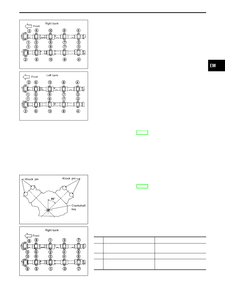
g.
Remove camshaft.
Loosen and remove the camshaft bolts following the order
shown in the figure.
Be sure to mark the camshaft bracket installation position
before removing the camshaft.
SEM446F
4.
Remove rocker arms.
5.
Remove hydraulic lash adjusters. Refer to “Disassembly” in
“CYLINDER HEAD” (EM-33).
SEM473F
Camshaft Installation
I
Install in reverse order of removal. Refer to “Installation” in
“CYLINDER HEAD” (EM-40).
I
Install camshaft knock pins in the positions shown in the fig-
ure.
SEM447F
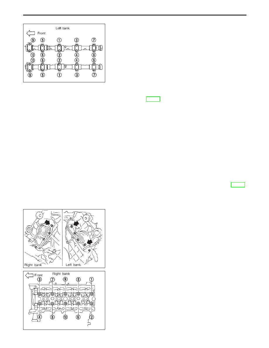
I
Tightening procedure
Tighten the camshaft brackets in the following steps.
Step
Tightening torque
Tightening order
1
2 N
⋅
m (0.2 kg-m, 17 in-lb)
Tighten in the order of
q
9
to
q
10
,
then tighten
q
1
to
q
8
.
2
6 N
⋅
m (0.6 kg-m, 52 in-lb)
Tighten in the numerical order.
3
11.8 - 13.7 N
⋅
m (1.20 - 1.40 kg-m,
104.2 - 121.5 in-lb)
Tighten in the numerical order.
I
Tighten in numerical order shown in the figure.
GI
MA
LC
EC
FE
AT
PD
FA
RA
BR
ST
RS
BT
HA
EL
IDX
CYLINDER HEAD
Camshaft Removal (Cont’d)
EM-31
SEM448F
Cylinder Head Assembly Removal
1.
Remove engine assembly from vehicle. Refer to “ENGINE
REMOVAL” (EM-43).
2.
Remove exhaust manifold.
3.
Drain all coolant from drain plugs on left and right side of cyl-
inder block.
4.
Remove the following parts.
I
Intake manifold collector.
I
Ignition coil sub-harness.
I
Ignition coils.
I
Spark plugs.
5.
Remove fuel tube assembly.
6.
Remove intake manifold.
7.
Remove rocker cover.
8.
Set No. 1 position at TDC on compression stroke.
9.
Remove camshaft position sensor.
10. Remove front cover upper.
11. Remove chain tensioner.
12. Remove camshaft sprocket.
13. Remove idler sprocket bolt. Refer to “TIMING CHAIN” (EM-15)
for procedures 5 to 13.
I
Apply paint to camshaft and idler sprockets for alignment
during installation.
SEM449F
14. Remove cylinder head sub-bolts.
Be careful during installation because the bolt (indicated by the
arrow) dimensions is different from others.
SEM450F
15. Loosen cylinder head bolts following the order shown in the
figure and remove cylinder head.
CYLINDER HEAD
Camshaft Installation (Cont’d)
EM-32
Нет комментариевНе стесняйтесь поделиться с нами вашим ценным мнением.
Текст