Infiniti Q45 (FY33). Manual — part 100
SBR401E
SBR402E
SBR403E
q
A
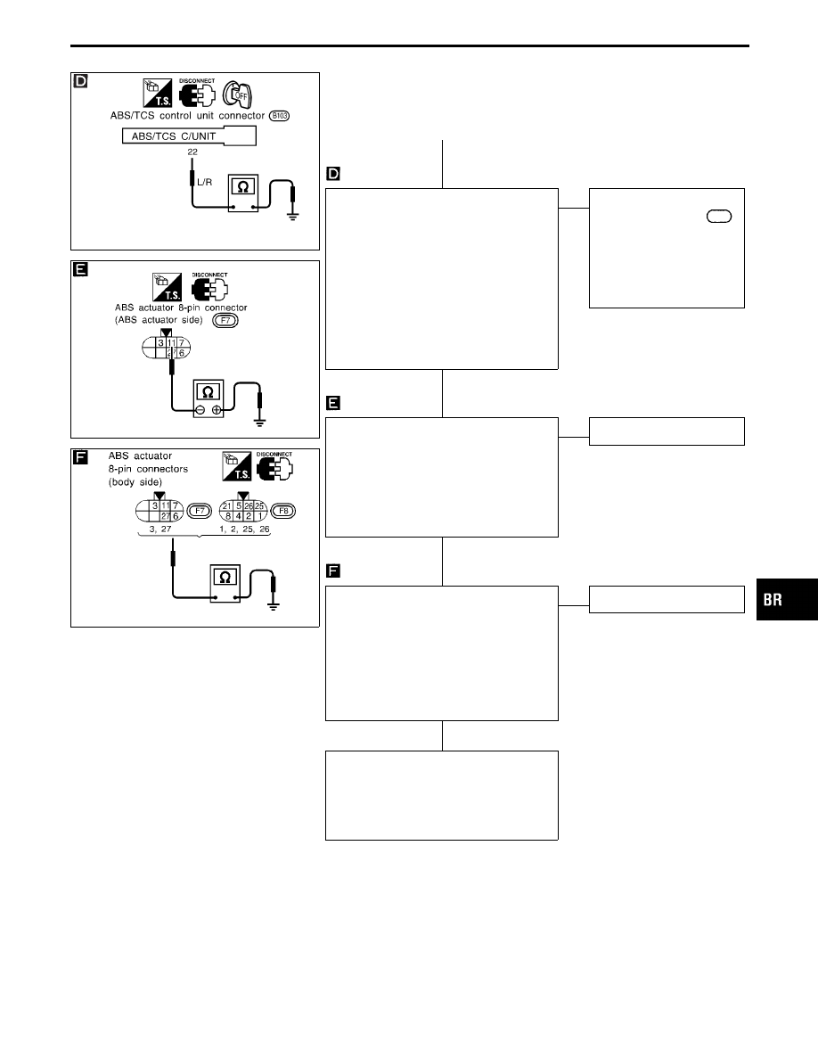
GROUND-SHORT CHECK FOR WARN-
ING LAMP CIRCUIT.
----------------------------------------------------------------------------------------------------------------------------------------------------------------------------------------------------------------------------------------------------------------------------------------------------------------
1. Turn ignition switch “OFF”.
2. Disconnect connectors from ABS/TCS
control unit and ABS actuator 8-pin con-
nector.
3. Check continuity between ABS/TCS
control unit connector terminal
q
22
and
body ground.
Continuity should not exist.
OK
E
NG
Check the following.
I
Harness connector
B103
I
Harness for open or
short between ABS/TCS
control unit and fuse
If NG, repair harness or
connectors.
1. Disconnect actuator ground terminal
and ABS actuator 8-pin connector.
2. Check continuity between ABS actuator
8-pin connector (ABS actuator side)
terminal
q
11
and body ground.
Continuity should not exist.
Note: Pay attention to tester polarity*.
OK
E
NG
Replace ABS actuator.
SOLENOID VALVE CIRCUIT
----------------------------------------------------------------------------------------------------------------------------------------------------------------------------------------------------------------------------------------------------------------------------------------------------------------
1. Disconnect ABS actuator 6-pin connec-
tor.
2. Check continuity between each ABS
actuator 8-pin connector (ABS actuator
side) terminals and body ground.
Continuity should not exist.
OK
E
NG
Replace ABS actuator.
Check control unit pin terminals for dam-
age or the connection of control unit har-
ness connector.
Reconnect control unit harness connector.
Then retest.
*: Specifications may vary depending on the type of tester.
Before performing this inspection, refer to the instruction manual of the
tester.
GI
MA
EM
LC
EC
FE
AT
PD
FA
RA
ST
RS
BT
HA
EL
IDX
TROUBLE DIAGNOSES FOR SYMPTOMS
Diagnostic Procedure 26 (ABS warning lamp
stays on when ignition switch is turned on.)
(Cont’d)
H
H
H
H
BR-117

SBR404E
q
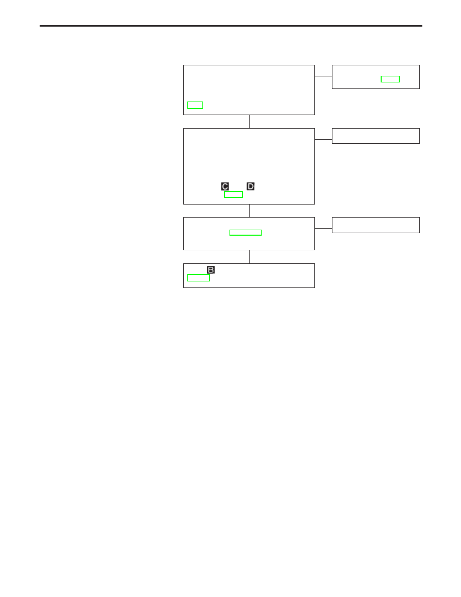
B
Replace 7.5A
31
fuse.
Does the fuse blow out when ignition
switch is turned “ON”?
Yes
E
No
Inspection end
CONTROL UNIT POWER SUPPLY
CIRCUIT
----------------------------------------------------------------------------------------------------------------------------------------------------------------------------------------------------------------------------------------------------------------------------------------------------------------
1. Disconnect control unit connector.
2. Check continuity between control unit
connector terminal
108
and body
ground.
Continuity should not exist.
OK
E
NG
Check the following.
I
Harness connector
B103
I
Harness for open or
short between ABS/TCS
control unit and fuse
If NG, repair harness or
connectors.
Check control unit pin terminals for dam-
age or the connection of control unit har-
ness connector.
Reconnect control unit harness connector.
Then retest.
TROUBLE DIAGNOSES FOR SYMPTOMS
Diagnostic Procedure 26 (ABS warning lamp
stays on when ignition switch is turned on.)
(Cont’d)
H
H
H
BR-118

SBR816D
Diagnostic Procedure 27 (TCS OFF switch is
inoperative.)
SBR405E
SBR696D
SBR697D
CHECK TCS OFF SWITCH.
----------------------------------------------------------------------------------------------------------------------------------------------------------------------------------------------------------------------------------------------------------------------------------------------------------------
Refer to TCS OFF SWITCH in Electrical
Components Inspection, BR-126.
OK
E
NG
Replace TCS OFF switch.
I
Disconnect connector from ABS/TCS
control unit.
I
Check continuity between terminal
q
13
for ABS/TCS control unit connector and
terminal
q
1
for TCS OFF switch con-
nector.
Continuity should exist.
OK
E
NG
Check the following.
I
Harness connectors
B103
,
N7
I
Harness for open or
short between TCS OFF
switch terminal (body
side) and ABS/TCS con-
trol unit
If NG, repair harness or
connectors.
I
Check continuity between terminal
q
1
for TCS OFF switch connector and
ground.
Continuity should not exist.
OK
E
NG
Repair harness and con-
nectors.
I
Check continuity between terminal
q
2
for TCS OFF switch connector and
ground.
Continuity should exist.
OK
E
NG
Repair harness and con-
nectors.
Preliminary check (Basic inspection 3),
BR-48
GI
MA
EM
LC
EC
FE
AT
PD
FA
RA
ST
RS
BT
HA
EL
IDX
TROUBLE DIAGNOSES FOR SYMPTOMS
H
H
H
H
BR-119
Diagnostic Procedure 28
(ABS works frequently.)
CHECK BRAKE FLUID PRESSURE.
----------------------------------------------------------------------------------------------------------------------------------------------------------------------------------------------------------------------------------------------------------------------------------------------------------------
Check brake fluid pressure distribution.
Refer to proportioning valve inspection,
BR-9.
OK
E
NG
Perform Preliminary
Check, refer to BR-48.
CHECK WHEEL SENSOR.
----------------------------------------------------------------------------------------------------------------------------------------------------------------------------------------------------------------------------------------------------------------------------------------------------------------
1. Check wheel sensor connector for ter-
minal damage or loose connections.
2. Perform wheel sensor mechanical
check.
Refer to
and
in Diagnostic Pro-
cedure 7, BR-88.
OK
E
NG
Repair.
Check front axles for excessive loose-
ness. Refer to FA section (“Front Wheel
Bearing”, “ON-VEHICLE SERVICE”).
OK
E
NG
Repair.
Go to
in Diagnostic Procedure 29,
TROUBLE DIAGNOSES FOR SYMPTOMS
H
H
H
BR-120
Нет комментариевНе стесняйтесь поделиться с нами вашим ценным мнением.
Текст