Infiniti Q45 (FY33). Manual — part 222
SEF599K
SEF320U
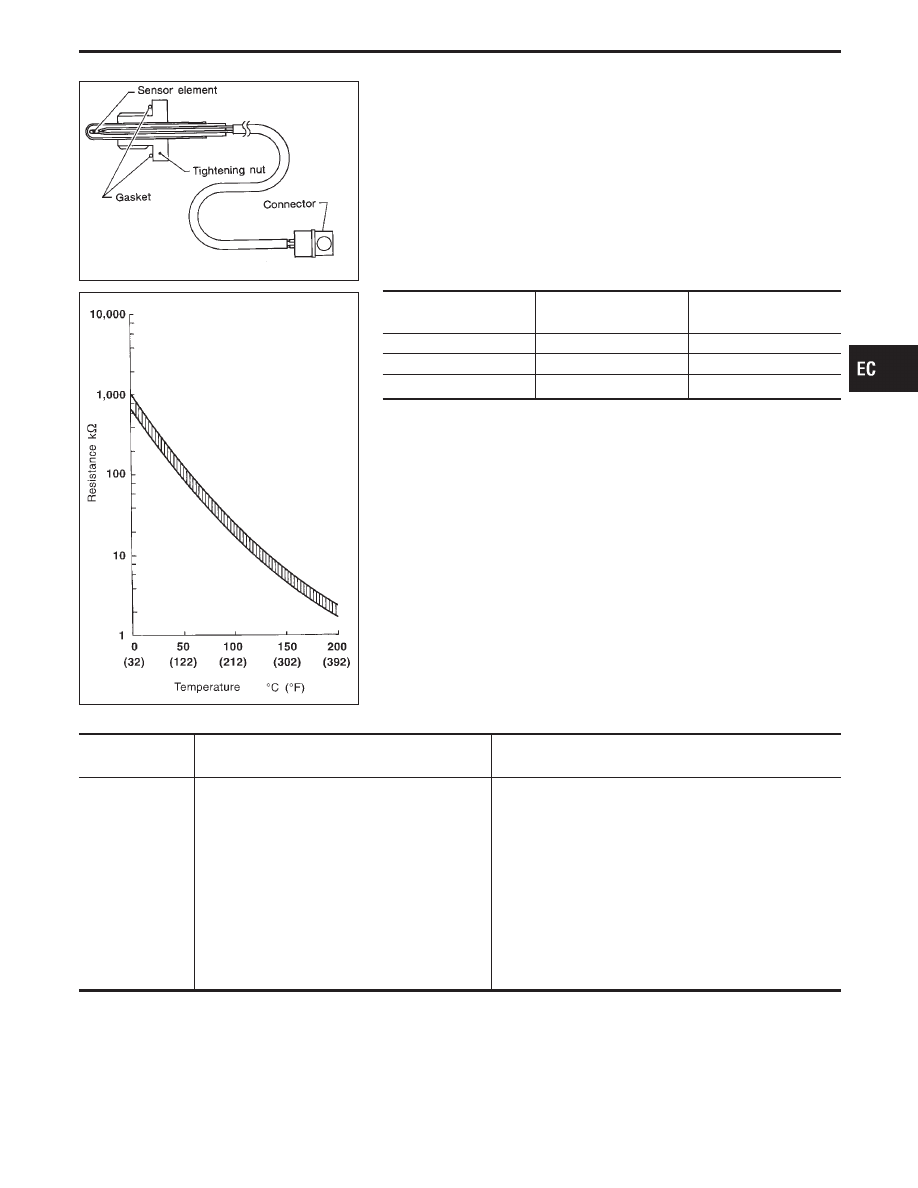
EGR Temperature Sensor
COMPONENT DESCRIPTION
The EGR temperature sensor detects temperature changes in the
EGR passage way. When the EGR valve opens, hot exhaust gases
flow, and the temperature in the passage way changes. The EGR
temperature sensor is a thermistor that modifies a voltage signal
sent from the ECM. This modified signal then returns to the ECM
as an input signal. As the temperature increases, EGR temperature
sensor resistance decreases.
This sensor is not directly used to control the engine system. It is
used only for the on board diagnosis.
EGR temperature
°C (°F)
Voltage*
(V)
Resistance
(M
Ω
)
0 (32)
4.61
0.68 - 1.11
50 (122)
2.53
0.092 - 0.12
100 (212)
0.87
0.017 - 0.024
*: These data are reference values and measured between ECM terminal
q
63
(EGR temperature sensor) and ground.
When EGR system is operating:
Voltage: 0 - 1.5V
CAUTION:
Do not use ECM ground terminals when measuring voltage.
Doing so may result in damage to the ECM’s transistor. Use a
ground other than ECM terminals such as the body ground.
ON BOARD DIAGNOSIS LOGIC
Diagnostic Trouble
Code No.
Malfunction is detected when .
Check Items
(Possible Cause)
P1401
0305
A) An excessively low voltage from the EGR tem-
perature sensor is sent to ECM, even when
engine coolant temperature is low.
. . . . . . . . . . . . . . . . . . . . .
I
Harness or connectors
(The EGR temperature sensor circuit is shorted.)
I
EGR temperature sensor
I
Malfunction of EGR function, EGRC-BPT valve or
EGRC-solenoid valve
. . . . . . . . . . . . . . . . . . . . . . . .
B) An excessively high voltage from the EGR
temperature sensor is sent to ECM, even
when engine coolant temperature is high.
I
Harness or connectors
(The EGR temperature sensor circuit is open.)
I
EGR temperature sensor
I
Malfunction of EGR function, EGRC-BPT valve or
EGRC-solenoid valve
GI
MA
EM
LC
FE
AT
PD
FA
RA
BR
ST
RS
BT
HA
EL
IDX
TROUBLE DIAGNOSIS FOR DTC P1401
EC-417
SEF279Y
DIAGNOSTIC TROUBLE CODE CONFIRMATION
PROCEDURE
Perform “Procedure for malfunction A” first. If DTC cannot be
confirmed, perform “Procedure for malfunction B”.
NOTE:
If “DIAGNOSTIC TROUBLE CODE CONFIRMATION PROCE-
DURE” has been previously conducted, always turn ignition
switch “OFF” and wait at least 5 seconds before conducting
the next test.
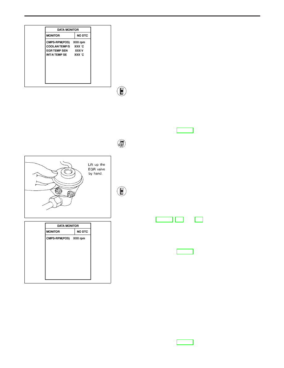
Procedure for malfunction A
1) Turn ignition switch “ON”.
2) Select “DATA MONITOR” mode with CONSULT-II.
3) Verify that engine coolant temperature is less than 40°C
(104°F).
If the engine coolant temperature is above the range,
cool the engine down.
4) Start engine and let it idle for at least 8 seconds.
5) If 1st trip DTC is detected, go to “DIAGNOSTIC
PROCEDURE”, EC-421.
------------------------------------------------------------------------------------------------------------------------------------------------------------------------------------------------------------------------------------------------------ OR ------------------------------------------------------------------------------------------------------------------------------------------------------------------------------------------------------------------------------------------------------
Follow the procedure “With CONSULT-II” above.
SEF360Q
SEF392X
Procedure for malfunction B
CAUTION:
Always drive vehicle at a safe speed.
TESTING CONDITION:
Always perform the test at temperature above −10°C (14°F).
1) Start engine and warm it up to normal operating tem-
perature.
2) Run engine at idle for at least 2 minutes.
3) Confirm that EGR valve is not lifting.
If the check result is NG, go to “TROUBLE DIAG-
NOSES FOR DTC P0400, P0402 and P1402”. (See
pages EC-281, and 423.)
4) Select “DATA MONITOR” mode with CONSULT-II.
5) Read “EGR TEMP SEN” at about 1,500 rpm while hold-
ing the EGR valve in full open position by hand.
Voltage should decrease to less than 1.0V.
If the check result is NG, go to “DIAGNOSTIC
PROCEDURE”, EC-421.
If the check result is OK, go to following step.
6) Turn ignition switch “OFF” and wait at least 5 seconds.
7) Turn ignition switch “ON”.
8) Check the output voltage of “THRTL POS SEN” at
closed throttle position and note it.
9) Start engine (TCS switch “OFF”).
10) Maintain the following conditions for at least 5 consecu-
tive seconds.
CMPS-RPM (POS): 1,200 - 2,200 rpm
VHCL SPEED SE: 10 km/h (6 MPH) or more
B/FUEL SCHDL: 3.3 - 4.5 msec
THRTL POS SEN: X − (X + 0.52) V
X = Voltage value measured at
step 7)
Selector lever: Suitable position
11) If 1st trip DTC is detected, go to “DIAGNOSTIC
PROCEDURE”, EC-421.
TROUBLE DIAGNOSIS FOR DTC P1401
EGR Temperature Sensor (Cont’d)
EC-418
SEF360Q
SEF015V
------------------------------------------------------------------------------------------------------------------------------------------------------------------------------------------------------------------------------------------------------ OR ------------------------------------------------------------------------------------------------------------------------------------------------------------------------------------------------------------------------------------------------------
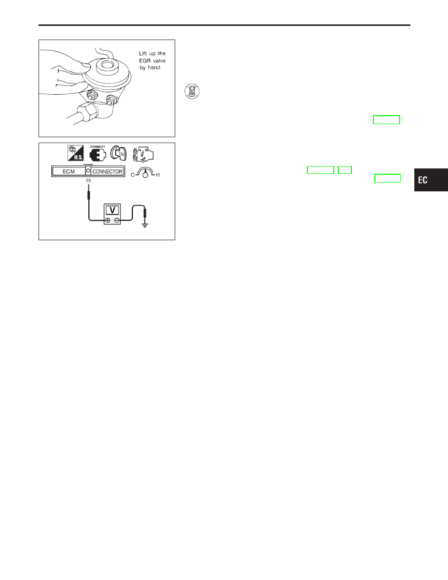
OVERALL FUNCTION CHECK
Use this procedure to check the overall function of the EGR tem-
perature sensor. During this check, a 1st trip DTC might not be
confirmed.
1) Start engine (TCS switch “OFF”) and warm it up to nor-
mal operating temperature.
2) Run engine at idle for at least 2 minutes.
3) Confirm that EGR valve is not lifting. If NG, go to
TROUBLE DIAGNOSES FOR DTC P1402, EC-423.
4) Check voltage between ECM terminal
q
75
and ground at
about 1,500 rpm with EGR valve lifted up to the full
position by hand.
Voltage should decrease to less than 1.0V.
5) If step 4 is OK, perform TROUBLE DIAGNOSES FOR
DTC P0400 and P1400, EC-286, 415.
6) If NG, go to “DIAGNOSTIC PROCEDURE”, EC-421.
GI
MA
EM
LC
FE
AT
PD
FA
RA
BR
ST
RS
BT
HA
EL
IDX
TROUBLE DIAGNOSIS FOR DTC P1401
EGR Temperature Sensor (Cont’d)
EC-419
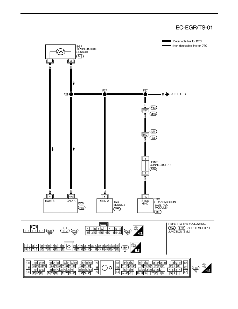
TEC069M
TROUBLE DIAGNOSIS FOR DTC P1401
EGR Temperature Sensor (Cont’d)
EC-420
Нет комментариевНе стесняйтесь поделиться с нами вашим ценным мнением.
Текст