Infiniti Q45 (FY33). Manual — part 58
SAT826A
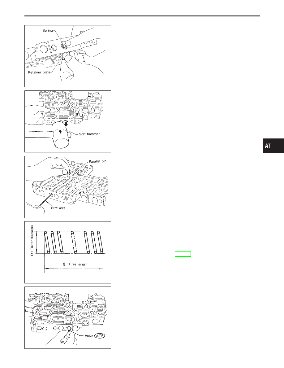
b.
Remove retainer plates while holding spring.
SAT827A
c.
Place mating surface of valve facedown, and remove internal
parts.
I
If a valve is hard to remove, lightly tap valve body with a
soft hammer.
I
Be careful not to drop or damage valves, sleeves, etc.
SAT828A
I
4-2 sequence valve and relay valve are located far back in
upper body. If they are hard to remove, carefully push them out
using stiff wire.
I
Be careful not to scratch sliding surface of valve with wire.
SAT829A
INSPECTION
Valve springs
I
Measure free length and outer diameter of each valve spring.
Also check for damage or deformation.
Inspection standard:
Refer to SDS, AT-277.
I
Replace valve springs if deformed or fatigued.
Control valves
I
Check sliding surfaces of valves, sleeves and plugs for dam-
age.
SAT830A
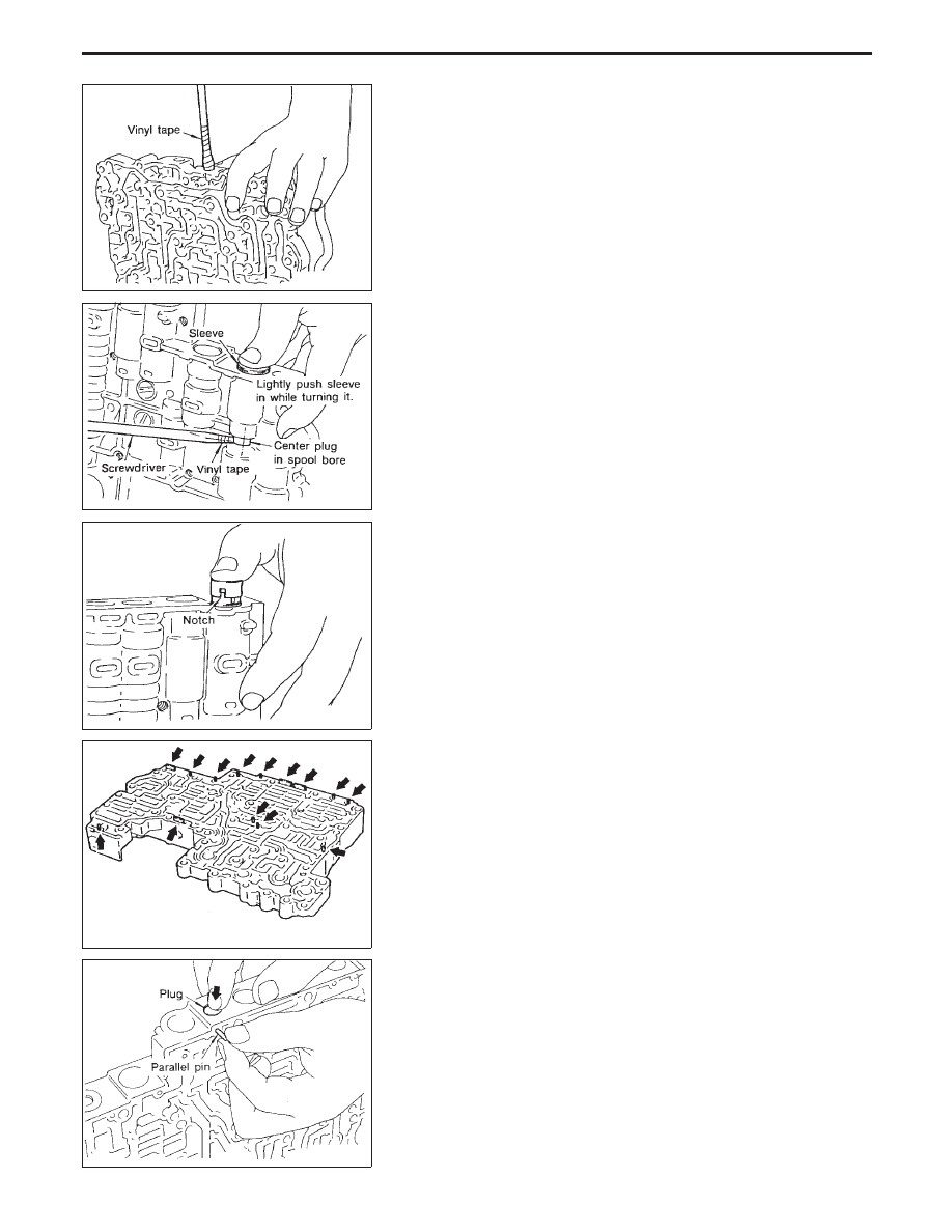
ASSEMBLY
1.
Lubricate the control valve body and all valves with ATF. Install
control valves by sliding them carefully into their bores.
I
Be careful not to scratch or damage valve body.
GI
MA
EM
LC
EC
FE
PD
FA
RA
BR
ST
RS
BT
HA
EL
IDX
REPAIR FOR COMPONENT PARTS
Control Valve Upper Body (Cont’d)
AT-229
SAT831A
I
Wrap a small screwdriver with vinyl tape and use it to insert the
valves into proper position.
SAT832A
Pressure regulator valve
I
If pressure regulator plug is not centered properly, sleeve can-
not be inserted into bore in upper body.
If this happens, use vinyl tape wrapped screwdriver to center
sleeve until it can be inserted.
I
Turn sleeve slightly while installing.
SAT833A
Accumulator control plug
I
Align protrusion of accumulator control sleeve with notch in
plug.
I
Align parallel pin groove in plug with parallel pin, and install
accumulator control valve.
SAT834A
2.
Install parallel pins and retainer plates.
SAT823A
I
While pushing plug, install parallel pin.
REPAIR FOR COMPONENT PARTS
Control Valve Upper Body (Cont’d)
AT-230
SAT835A
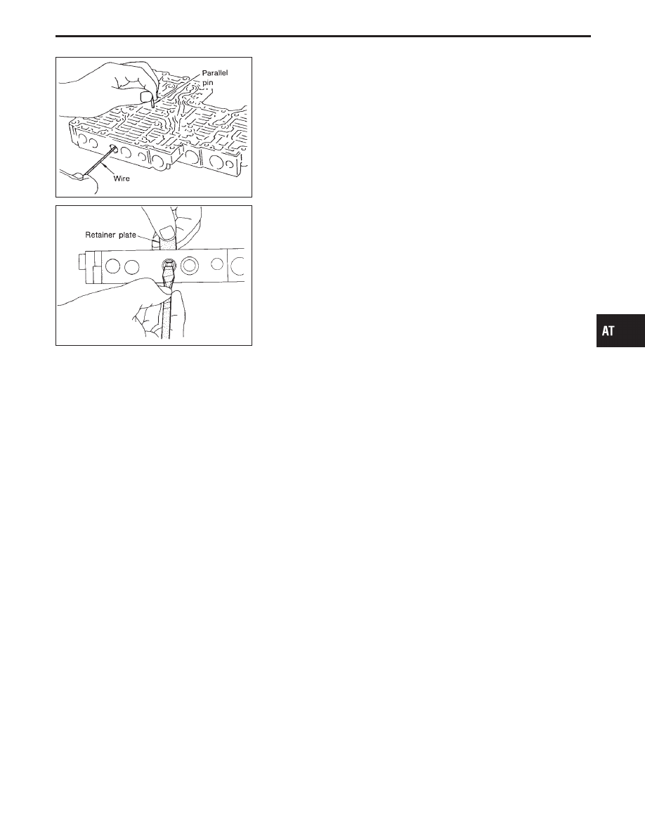
4-2 sequence valve and relay valve
I
Push 4-2 sequence valve and relay valve with wire wrapped in
vinyl tape to prevent scratching valve body. Install parallel pins.
SAT836A
I
Insert retainer plate while pushing spring.
GI
MA
EM
LC
EC
FE
PD
FA
RA
BR
ST
RS
BT
HA
EL
IDX
REPAIR FOR COMPONENT PARTS
Control Valve Upper Body (Cont’d)
AT-231
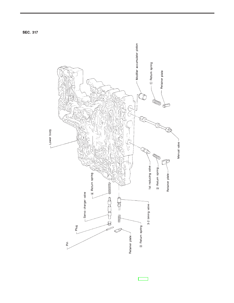
Control Valve Lower Body
Numbers preceding valve springs correspond with those shown in SDS table on page AT-277.
Apply ATF to all components before their installation.
SAT997GC
REPAIR FOR COMPONENT PARTS
AT-232
Нет комментариевНе стесняйтесь поделиться с нами вашим ценным мнением.
Текст