Infiniti Q45 (FY33). Manual — part 318

System Description
POWER SUPPLY AND GROUND
When ignition switch is in the ON or START position, power is supplied
I
through 7.5A fuse [No.
32
, located in the fuse block (J/B)]
I
to ASCD hold unit terminal
q
1
.
When MAIN switch is depressed, ground is supplied
I
to ASCD hold unit terminal
q
2
I
through ASCD steering switch terminal
q
4
.
If those two signals are input, ASCD hold unit supplies power
I
to ASCD control unit terminal
q
4
,
I
to ASCD control unit terminal
q
5
(through ASCD brake switch and park/neutral position relay) and
I
to combination meter terminal
q
45
to illuminate CRUISE indicator.
ASCD hold unit keeps power supply until any of following condition exists.
I
Ignition switch is returned to the ACC or OFF position.
I
MAIN switch is depressed again.
Ground is supplied
I
to ASCD hold unit terminal
q
4
and
I
to ASCD control unit terminal
q
3
I
through body grounds
M14
and
M47
.
OPERATION
Set operation
To activate the ASCD, all of following conditions must exist.
I
Power supply to ASCD control unit terminal
q
4
I
Power supply to ASCD control unit terminal
q
5
(Brake pedal is released and A/T selector lever is in other
than P and N position.)
I
Vehicle speed is between 48 km/h (30 MPH) and 144 km/h (89 MPH). (Signal from combination meter)
When the SET/COAST switch is depressed, power is supplied
I
from ASCD steering switch terminal
q
2
I
to ASCD control unit terminal
q
2
.
And then ASCD pump is activated to control throttle wire and ASCD control unit supply power
I
to combination meter terminal
q
46
to illuminate SET indicator.
A/T overdrive control during cruise control driving
When the vehicle speed is approximately 8 km/h (5 MPH) below set speed, a signal is sent
I
from ASCD control unit terminal
q
12
I
to TCM (transmission control module) terminal
q
40
.
When this occurs, the TCM (transmission control module) cancels overdrive.
After vehicle speed is approximately 3 km/h (2 MPH) above set speed, overdrive is reactivated.
Coast operation
When the SET/COAST switch is depressed during cruise control driving, ASCD actuator returns the throttle
cable to decrease vehicle set speed until the switch is released. And then ASCD will keep the new set speed.
Accel operation
When the RESUME/ACCEL switch is depressed, power is supplied
I
from ASCD steering switch terminal
q
3
I
to ASCD control unit terminal
q
1
.
If the RESUME/ACCEL switch is depressed during cruise control driving, ASCD actuator pulls the throttle cable
to increase the vehicle speed until the switch is released or vehicle speed is reached to maximum controlled
speed by the system. And then ASCD will keep the new set speed.
Cancel operation
When any of following condition exists, cruise operation will be canceled. (CRUISE indicator will continue to
illuminate.)
I
CANCEL switch is depressed. (Power supply to ASCD control unit terminals
q
1
and
q
2
)
I
Brake pedal is depressed. (Power supply to ASCD control unit terminal
q
11
from stop lamp switch)
I
Brake pedal is depressed or A/T selector lever is shifted to P or N position. (Power supply to ASCD con-
trol unit terminal
q
5
is interrupted.)
If MAIN switch is depressed during ASCD is activated, all of ASCD operation will be canceled and vehicle
speed memory will be erased.
GI
MA
EM
LC
EC
FE
AT
PD
FA
RA
BR
ST
RS
BT
HA
IDX
AUTOMATIC SPEED CONTROL DEVICE (ASCD)
EL-263

Resume operation
When the RESUME/ACCEL switch is depressed after cancel operation other than depressing MAIN switch is
performed, vehicle speed will return to last set speed. To resume vehicle set speed, vehicle condition must
meet following conditions.
I
Brake pedal is released.
I
A/T selector lever is in other than P and N position.
I
Vehicle speed is between 48 km/h (30 MPH) and 144 km/h (89 MPH).
ASCD PUMP OPERATION
The ASCD pump consists of a vacuum motor, an air valve and a release valve. When the ASCD activates,
power is supplied
I
from terminal
q
8
of ASCD control unit
I
to ASCD pump terminal
q
1
.
Ground is supplied to vacuum motor, air valve and release valve from ASCD control unit depending on the
operated condition as shown in the below table.
The pump is connected to ASCD actuator by vacuum hose. When the ASCD pump is activated, the ASCD
pump vacuum the diaphragm of ASCD actuator to control throttle cable.
Air valve*
Release valve*
Vacuum motor
Actuator inner pres-
sure
ASCD not operating
Open
Open
Stopped
Atmosphere
ASCD operating
Releasing throttle
cable
Open
Closed
Stopped
Vacuum (decrease)
Holding throttle
position
Closed
Closed
Stopped
Vacuum (hold)
Pulling throttle cable Closed
Closed
Operated
Vacuum (increase)
*: When power and ground is supplied, valve is closed.
AUTOMATIC SPEED CONTROL DEVICE (ASCD)
System Description (Cont’d)
EL-264
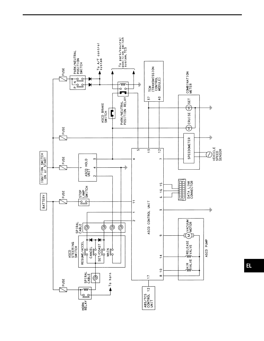
Schematic
TEL028M
GI
MA
EM
LC
EC
FE
AT
PD
FA
RA
BR
ST
RS
BT
HA
IDX
AUTOMATIC SPEED CONTROL DEVICE (ASCD)
EL-265
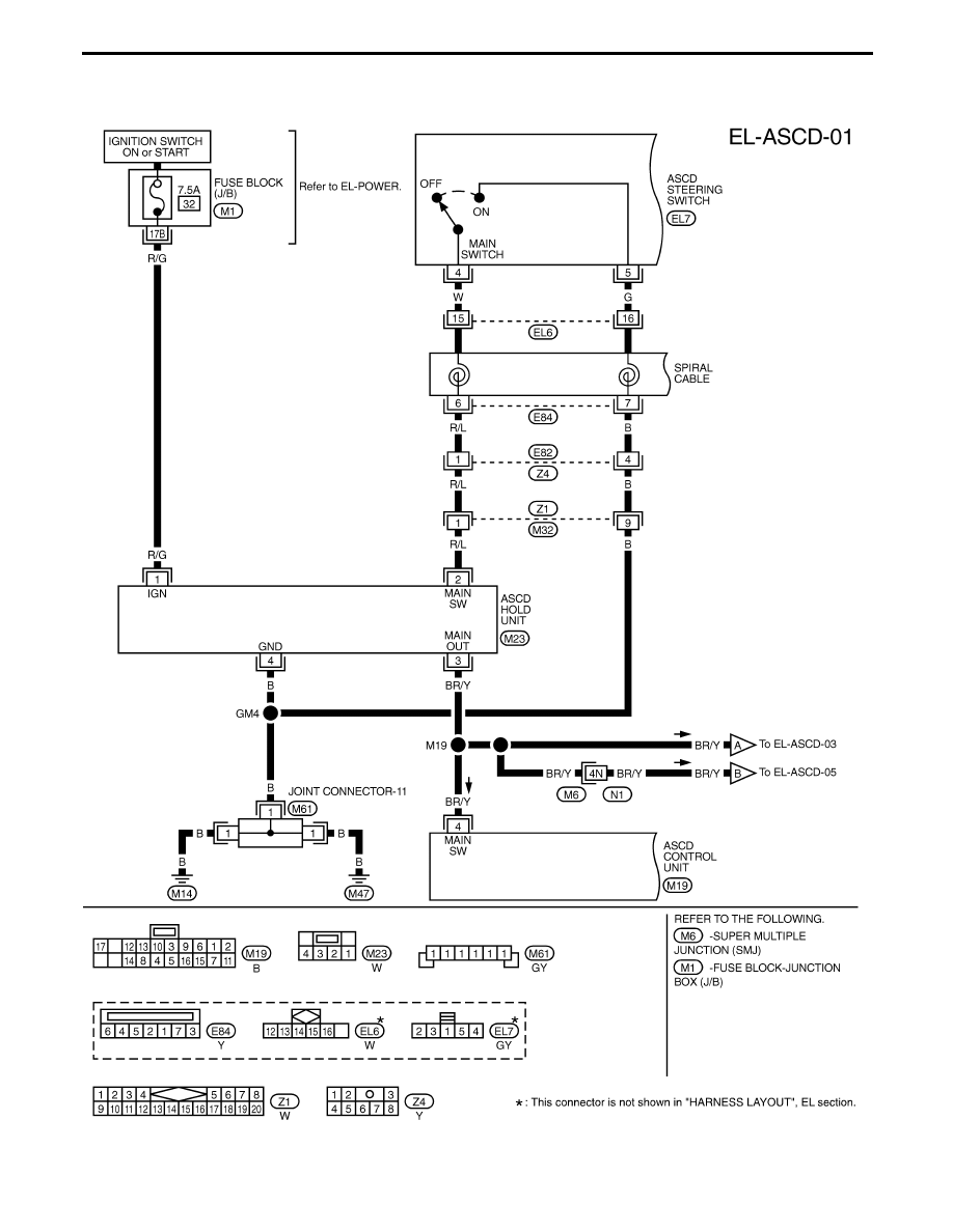
Wiring Diagram — ASCD —
TEL127M
AUTOMATIC SPEED CONTROL DEVICE (ASCD)
EL-266
Нет комментариевНе стесняйтесь поделиться с нами вашим ценным мнением.
Текст