Infiniti Q45 (FY33). Manual — part 489
RHA560FA
RHA927F
q
B
Note
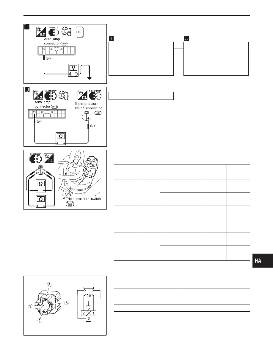
CHECK AUTO AMP. CIRCUIT
BETWEEN TRIPLE-PRESSURE
SWITCH AND AUTO AMP.
Do approx. 4 to 5 volts exist
between auto amp. harness termi-
nal No.
q
22
and body ground?
Yes
E
No
Check circuit continuity between
auto amp. harness terminal No.
q
22
and triple-pressure switch harness
terminal No.
q
4
.
Continuity should exist.
If OK, check harness for short.
Replace auto amp.
Note:
If the result is NG or No after checking circuit continuity, repair harness
or connector.
RHA942F
COMPONENT INSPECTION
Triple-pressure switch
Terminals
High-pressure side line
pressure
kPa (kg/cm
2
, psi)
Operation
Continuity
Low-pres-
sure side
q
1
-
q
4
Increasing to
152.0 - 201.0
(1.55 - 2.05, 22.0 - 29.2)
ON
Exists.
Decreasing to
152.0 - 201.0
(1.55 - 2.05, 22.0 - 29.2)
OFF
Does not
exist.
Medium-
pressure
side*
q
2
-
q
3
Increasing to
1,422 - 1,618
(14.5 - 16.5, 206 - 235)
ON
Exists.
Decreasing to
1,128 - 1,422
(11.5 - 14.5, 164 - 206)
OFF
Does not
exist.
High-pres-
sure side
q
1
-
q
4
Decreasing to
2,059 - 2,256
(21 - 23, 299 - 327)
ON
Exists.
Increasing to
2,648 - 2,844
(27 - 29, 384 - 412)
OFF
Does not
exist.
* For cooling fan motor operation.
SEF090M
A/C relay
Check continuity between terminal Nos.
q
3
and
q
5
.
Conditions
Continuity
12V direct current supply between
terminal Nos.
q
1
and
q
2
.
Yes
No current supply
No
If NG, replace relay.
GI
MA
EM
LC
EC
FE
AT
PD
FA
RA
BR
ST
RS
BT
EL
IDX
TROUBLE DIAGNOSES
Magnet Clutch Circuit (Cont’d)
H
H
HA-121
HA-0410D
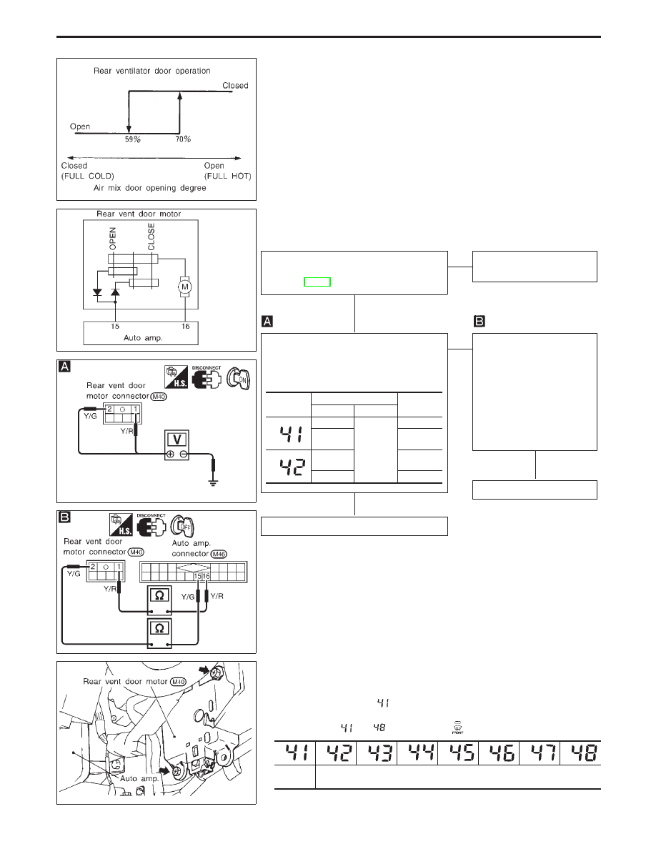
Rear Vent Door Motor Circuit
COMPONENT DESCRIPTION
Rear vent door is opened or closed by rear vent door motor. Rear
vent door operation is controlled by auto amplifier.
RHA175H
DIAGNOSTIC PROCEDURE
SYMPTOM: Rear vent door motor does not operate normally.
RHA695FA
RHA178H
CHECK MAIN POWER SUPPLY AND
GROUND CIRCUIT FOR AUTO AMP.
(Refer to HA-87.)
OK
E
NG
Repair Main Power Supply
and Ground Circuit.
Note
CHECK FOR AUTO AMP. OUTPUT.
Do approx. 12 volts exist between rear
ventilator door harness terminal Nos.
q
1
,
q
2
and body ground?
Yes
E
No
Check circuit continuity
between auto amp. harness
terminal No.
q
15
(
q
16
) and
rear ventilator door motor
harness terminal No.
q
2
(
q
1
).
Continuity should exist.
If OK, check harness for
short.
OK
Replace auto amp.
CHECK REAR VENT DOOR MOTOR.
Note:
If the result is NG or No after checking circuit continuity, repair harness
or connector.
RHA948F
COMPONENT INSPECTION
Rear vent door motor
1.
Set up code No.
in Self-diagnosis STEP 4.
2.
Check rear ventilator door operates properly when changing
code No.
to
by pushing
(DEF) switch.
Open
Close
Code No.
Terminal No.
Voltage
V
!
@
q
1
Body
ground
0
q
2
Approx.
12
q
1
Approx.
12
q
2
0
TROUBLE DIAGNOSES
H
H
H
HA-122
RHA164H
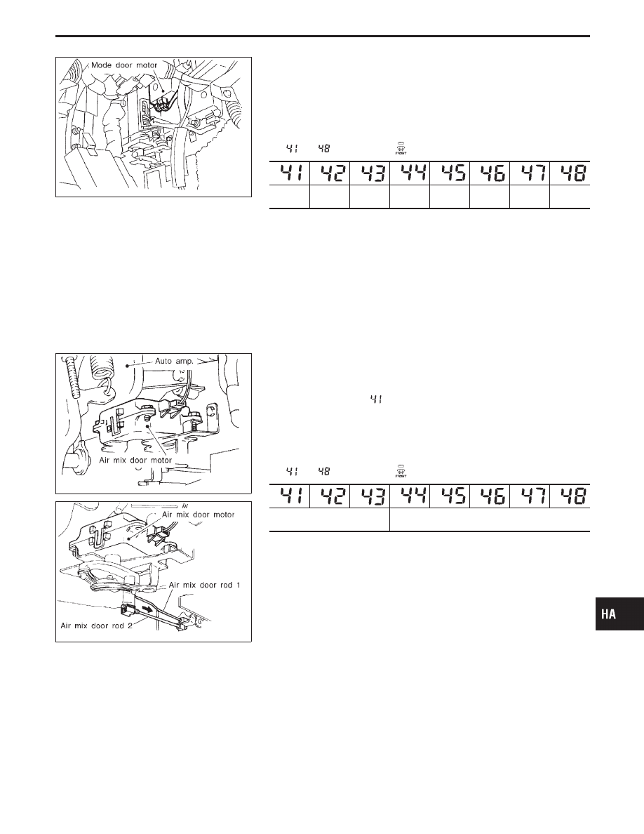
Control Linkage Adjustment
MODE DOOR
1.
Install mode door motor to heater unit and connect it to body
harness.
2.
Attach mode door motor rod to side link holder.
3.
Check mode door operates properly when changing code No.
to
by pushing
(DEF) switch.
VENT
VENT
B/L
B/L
B/L2
FOOT
F/D
DEF
RHA176H
RHA177H
AIR MIX DOOR
1.
Install air mix door motor to heater unit and connect it to body
harness.
2.
Set up code No.
in Self-diagnosis STEP 4.
3.
Move air mix door lever by hand and hold it at full cold posi-
tion.
4.
Attach air mix door rod 1 to rod holder.
5.
Push air mix door rod 2 in arrow direction.
6.
Check air mix door operates properly when changing code No.
to
by pushing
(DEF) switch.
Full Cold
Full Hot
GI
MA
EM
LC
EC
FE
AT
PD
FA
RA
BR
ST
RS
BT
EL
IDX
TROUBLE DIAGNOSES
HA-123
RHA938F
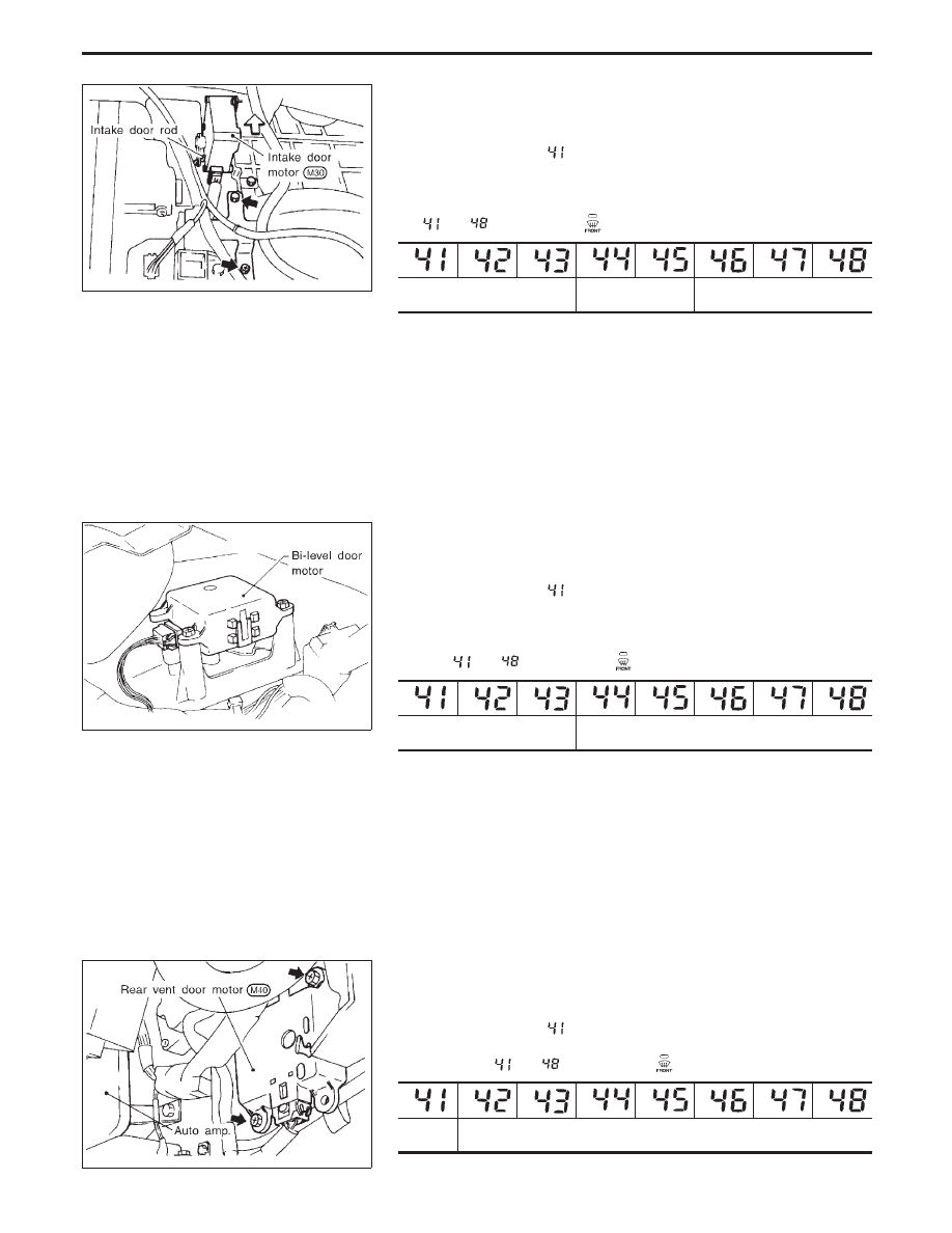
INTAKE DOOR
1.
Install intake door motor to intake unit and connect it to body
harness.
2.
Set up code No.
in Self-diagnosis STEP 4.
3.
Move intake door link by hand and hold it at REC position.
4.
Attach intake door lever to rod holder.
5.
Check intake door operates properly when changing code No.
to
by pushing
(DEF) switch.
REC
20% FRE
FRE
RHA940F
BI-LEVEL DOOR
1.
Install bi-level door motor to heater unit and connect it to body
harness.
2.
Set up code No.
in Self-diagnosis STEP 4.
3.
Move water valve rod by hand and hold it at closed position.
4.
Attach water valve rod to rod holder.
5.
Check bi-level door operates properly when changing code
No.
to
by pushing
(DEF) switch.
Open
Close
RHA948F
REAR VENTILATOR DOOR
1.
Install rear ventilator door motor to heater unit and connect it
to body harness.
2.
Set up code No.
in Self-diagnosis STEP 4.
3.
Check rear ventilator door operates properly when changing
code No.
to
by pushing
(DEF) switch.
Open
Close
TROUBLE DIAGNOSES
Control Linkage Adjustment (Cont’d)
HA-124
Нет комментариевНе стесняйтесь поделиться с нами вашим ценным мнением.
Текст