Infiniti Q45 (FY33). Manual — part 334
SEL519W
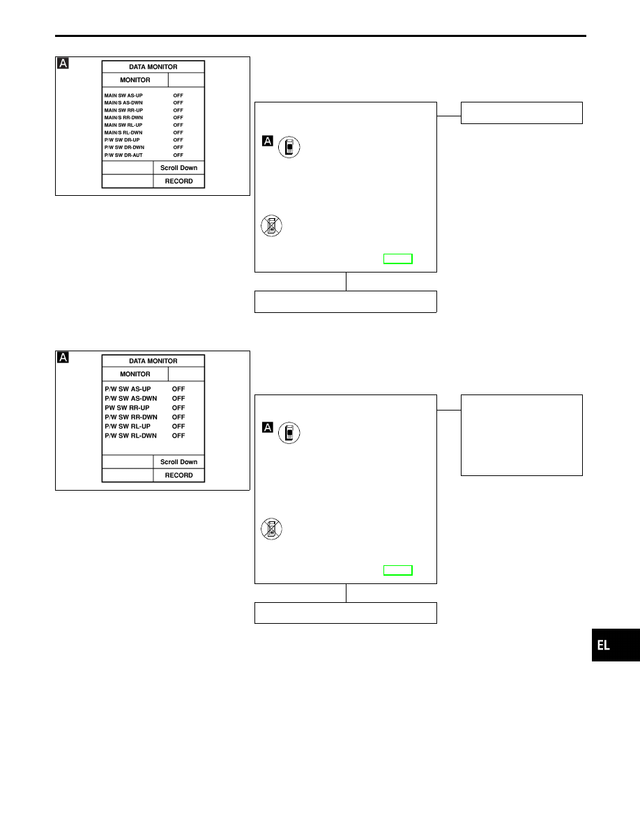
DIAGNOSTIC PROCEDURE 3
[Power window main switch (Driver side, Passenger side, Rear
LH, RH) check]
CHECK DRIVER’S DOOR TRIM POWER
WINDOW MAIN SWITCH INPUT SIG-
NAL.
CONSULT-II
See “MAIN SW UP or DOWN” in DATA
MONITOR mode.
“MAIN SW UP or DOWN” should
change from “OFF” to “ON” when
pushing power window main switches.
-------------------------------------------------------------------------------------------------------------------------------------- OR --------------------------------------------------------------------------------------------------------------------------------------
ON BOARD
Check power window main switch opera-
tion in Switch monitor (Mode II) mode.
(Refer to On board Diagnosis, EL-299.)
OK
E
NG
Replace LCU01.
Power window main switch is OK.
SEL520W
DIAGNOSTIC PROCEDURE 4
[Power window sub-switch (Passenger side, Rear LH, RH)
check]
CHECK POWER WINDOW SUB-SWITCH
INPUT SIGNAL.
CONSULT-II
See “P/W SW UP or DOWN” in DATA
MONITOR mode.
“P/W SW UP or DOWN” should change
from “OFF” to “ON” when each sub-
switch is turned ON.
-------------------------------------------------------------------------------------------------------------------------------------- OR --------------------------------------------------------------------------------------------------------------------------------------
ON BOARD
Check power window sub-switch operation
in Switch monitor (Mode II) mode.
(Refer to On board Diagnosis, EL-299.)
OK
E
NG
Replace LCU for malfunc-
tioning portion.
---------------------------------------------------------------------------------------------------------------------------------------------------------------------------------------------------------
I
Passenger: LCU02
I
Rear LH: LCU04
I
Rear RH: LCU03
Power window sub-switch is OK.
GI
MA
EM
LC
EC
FE
AT
PD
FA
RA
BR
ST
RS
BT
HA
IDX
POWER WINDOW — IVMS
Trouble Diagnoses (Cont’d)
H
H
EL-327
SEL521W
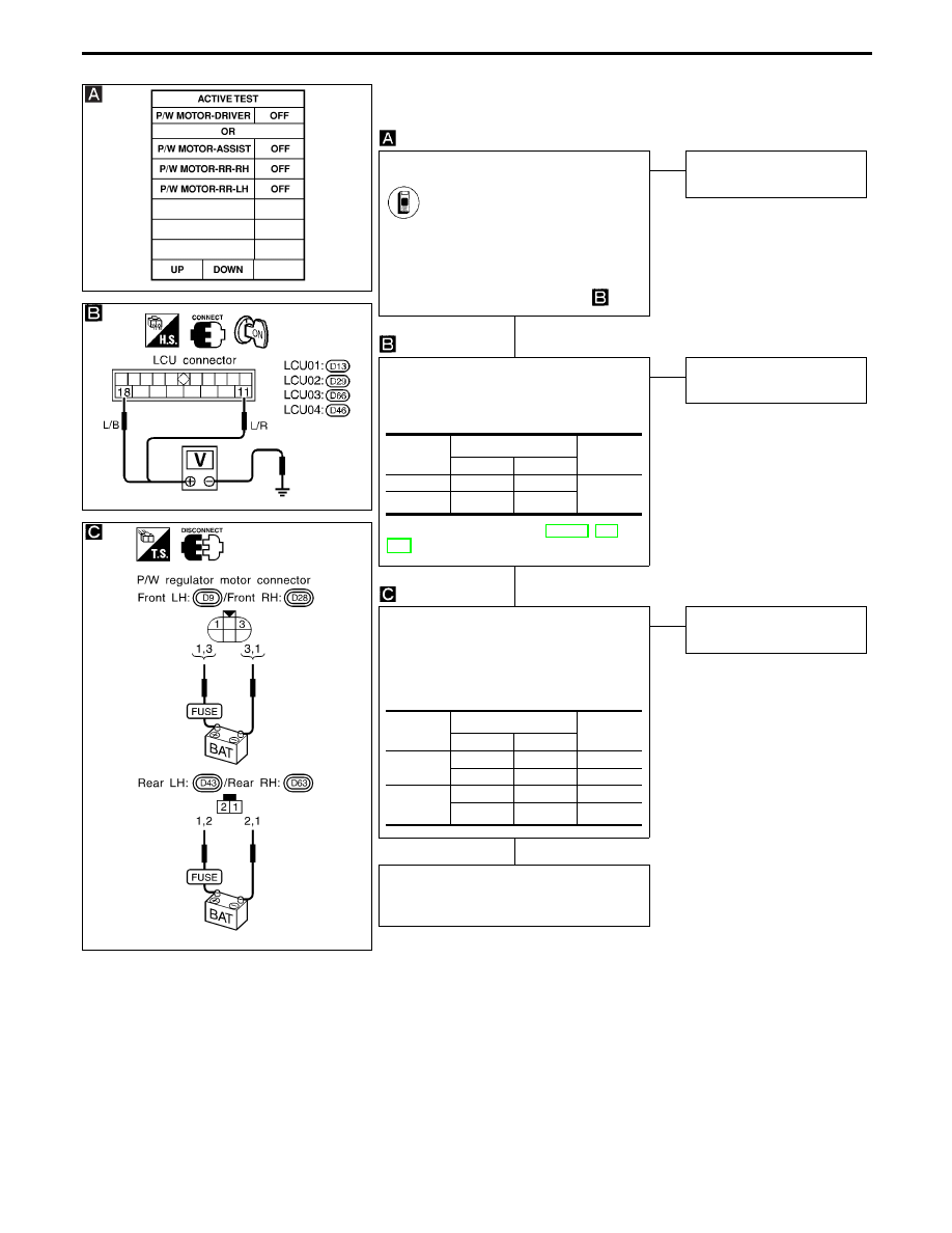
DIAGNOSTIC PROCEDURE 5
(Power window regulator check)
SEL568UA
SEL867W
POWER WINDOW REGULATOR ACTIVE
TEST.
CONSULT-II
See “P/W MOTOR” in ACTIVE TEST
mode.
Perform operation shown on display.
Power window motor should operate.
NOTE: If CONSULT-II is not available,
start with diagnostic procedure
.
NG
E
OK
Power window regulator is
OK.
CHECK LCU OUTPUT SIGNAL TO
POWER WINDOW REGULATOR.
Check voltage between LCU connector
terminals
q
11
or
q
18
and ground.
Refer to wiring diagram in EL-319, or
322.
OK
E
NG
Replace LCU for malfunc-
tioning portion.
CHECK POWER WINDOW REGULATOR
MOTOR.
1. Disconnect power window regulator
motor connector.
2. Apply 12V DC direct current to motor
and check operation.
OK
E
NG
Replace power window
regulator motor.
Check harness for open or short between
power window switch and power window
regulator motor.
Operation
Terminals
Voltage
!
@
Up
q
11
Ground
Battery
voltage
Down
q
18
Ground
Terminals
Operation
!
@
Front
q
1
q
3
Upward
q
3
q
1
Downward
Rear
q
1
q
2
Downward
q
2
q
1
Upward
POWER WINDOW — IVMS
Trouble Diagnoses (Cont’d)
H
H
H
EL-328
SEL949W
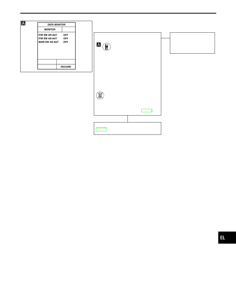
DIAGNOSTIC PROCEDURE 6
(Power window automatic switch check)
CHECK POWER WINDOW AUTO
SWITCH INPUT SIGNAL.
CONSULT-II
See “P/W SW DR-AUT/AS-AUT” and
“MAIN SW AS-AUT” in DATA MONITOR
mode.
“P/W SW DR-AUT/AS-AUT” and “MAIN
SW AS-AUT” should change from “ON”
to “OFF” when completely pushing in
or pulling out each power window
switch.
-------------------------------------------------------------------------------------------------------------------------------------- OR --------------------------------------------------------------------------------------------------------------------------------------
ON BOARD
Check power window switch auto opera-
tion in switch monitor (Mode II) mode.
(Refer to On board Diagnosis, EL-299.)
OK
E
NG
Replace LCU for malfunc-
tioning portion.
I
Driver: LCU01
I
Passenger: LCU02
Check encoder and limit switch. (Refer to
EL-331.)
GI
MA
EM
LC
EC
FE
AT
PD
FA
RA
BR
ST
RS
BT
HA
IDX
POWER WINDOW — IVMS
Trouble Diagnoses (Cont’d)
H
EL-329
SEL524W
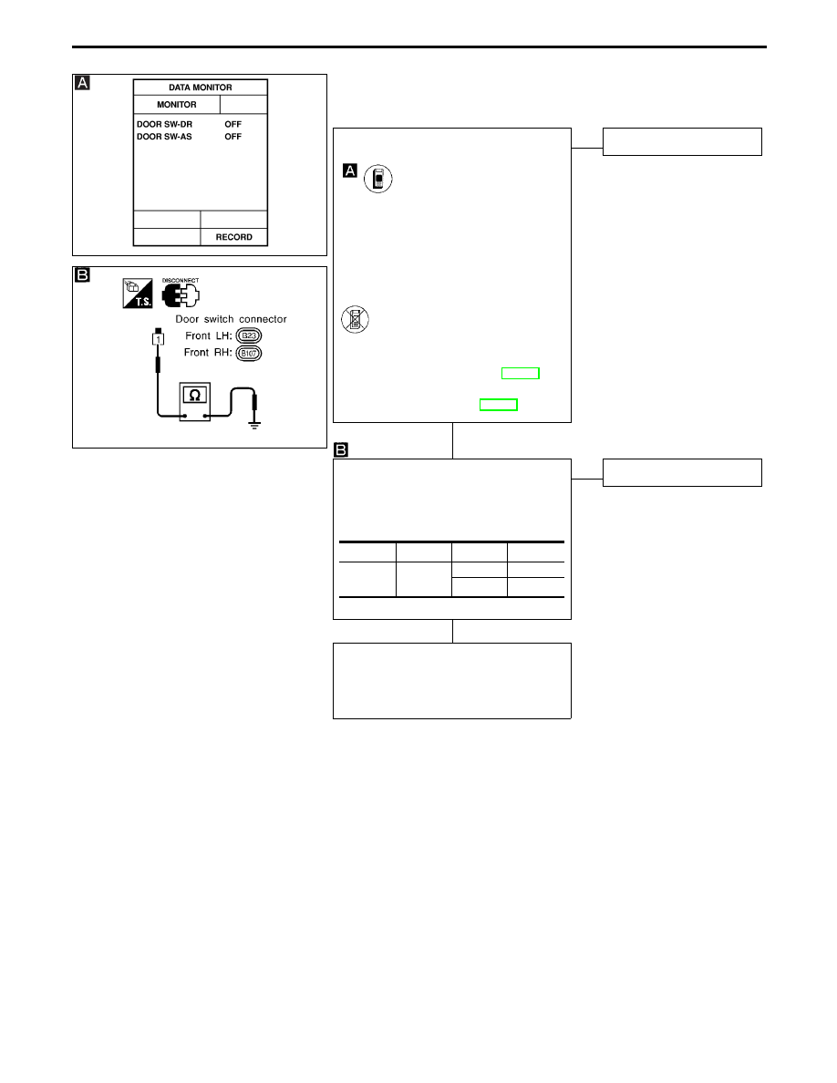
DIAGNOSTIC PROCEDURE 7
(Front door switch check)
SEL914U
CHECK FRONT DOOR SWITCH INPUT
SIGNAL.
CONSULT-II
See “DOOR SW” in DATA MONITOR
mode.
When door is open:
DOOR SW
ON
When door is closed:
DOOR SW
OFF
-------------------------------------------------------------------------------------------------------------------------------------- OR --------------------------------------------------------------------------------------------------------------------------------------
ON BOARD
Check front door switches in Switch moni-
tor (Mode II) mode.
(Refer to On board Diagnosis, EL-299.)
Refer to wiring diagram in EL-319.
NG
E
OK
Door switch is OK.
CHECK DOOR SWITCH.
1. Disconnect door switch connector.
2. Check continuity between terminal and
switch body ground.
OK
E
NG
Replace door switch.
Check the following.
I
Door switch ground condition
I
Harness for open or short between door
switch and BCM
Terminals
Condition
Continuity
Front door
switch
q
1
-
Ground
Pressed
No
Released
Yes
POWER WINDOW — IVMS
Trouble Diagnoses (Cont’d)
H
H
EL-330
Нет комментариевНе стесняйтесь поделиться с нами вашим ценным мнением.
Текст