Infiniti Q45 (FY33). Manual — part 388
I
When the radio wave from GPS satellites cannot be received,
for example, when the vehicle is in a tunnel, in a parking lot
inside building, under an elevated superhighway or near strong
power lines, the location may not be detected. Turbulent/
electric weather conditions may also affect positioning perfor-
mance. If something is placed on the antenna, the radio wave
from GPS satellites may not be received.
SEL688V
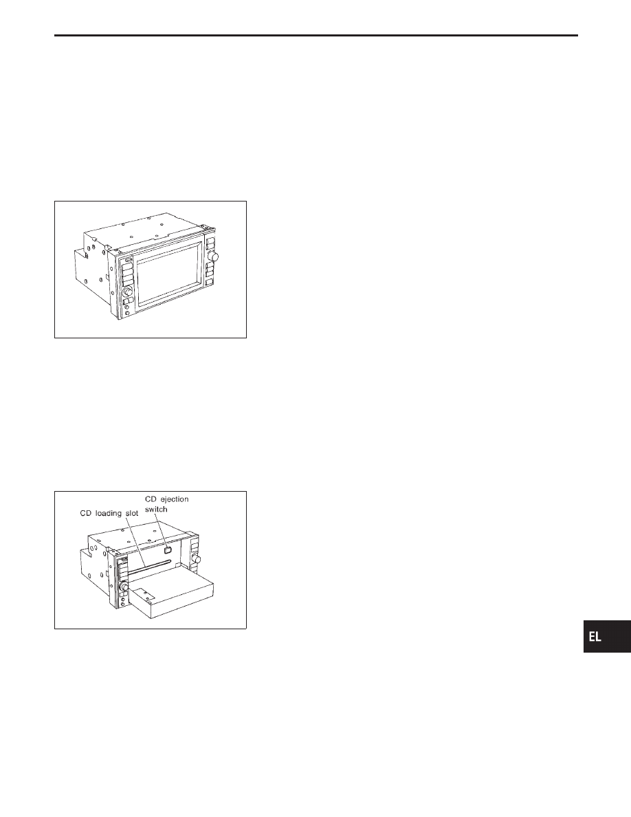
COMPONENT DESCRIPTION
Display & NAVI control unit
I
The gyro (angular speed sensor) and the CD-ROM drive are
built-in units that control the navigation functions.
I
Signals are received from the gyro, the vehicle speed sensor,
and the GPS antenna. Vehicle location is determined by com-
bining this data with the data contained in the CD-ROM map.
Locational information is shown on liquid crystal display panel.
I
Finger-operated touch switches are positioned on the liquid
crystal display panel for easy operation.
I
The touch switches used to control the equipment are beneath
a glass sheet and two resistance membranes at the top of the
liquid crystal display panel. The switches are sensitive to resis-
tance value where touched with your finger to detect operat-
ing status.
SEL689V
CD-ROM driver
Maps, traffic control regulations, and other pertinent information
can be easily red from the CD-ROM disc.
Note:
I
When removing the CD-ROM, allow it to remain open until the
liquid crystal display locks.
I
The liquid crystal display must be closed when the vehicle is
running.
I
Do not place cups, cans or other containers containing liquids
on top of the liquid crystal display.
Map CD-ROM
I
The map CD-ROM has maps, traffic control regulations, and
other pertinent information.
I
To improve CD-ROM map matching and route determination
functions, the CD-ROM uses an exclusive Nissan format.
Therefore, the use of a CD-ROM provided by other manufac-
turers cannot be used.
GI
MA
EM
LC
EC
FE
AT
PD
FA
RA
BR
ST
RS
BT
HA
IDX
NAVIGATION SYSTEM
System Description (Cont’d)
EL-543
SEL690V
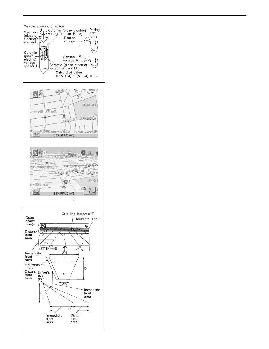
Gyro (Angular speed sensor)
I
The oscillator gyro sensor is used to detect changes in vehicle
steering angle.
I
The oscillator gyro periodically senses oscillatory variation at
the oscillation terminals. This variation is caused by changes
in the vehicle angular velocity. Voltage variations are sensed
by ceramic voltage sensors at the left and right sides of the
terminals. Vehicle angular velocity corresponds directly with
these changes in voltage.
I
The gyro is built into the display & navigation (NAVI) control
unit.
MAP DISPLAY
BIRDVIEW
R
SEL636X
BIRDVIEW
T
The BIRDVIEW
T
provides a detailed and easily seen display of
road conditions covering the vehicle’s immediate to distant area.
SEL691V
Description
I
Display area: Trapezoidal representation showing approximate
distances (Wn, D, and Wd).
I
Ten horizontal grid lines indicate display width while six verti-
cal grid lines indicate display depth and direction.
I
Drawing line area shows open space, depth, and immediate
front area. Each area is to a scale of approximately 5:6:25.
I
When the “ZM−” button is pushed, the view point height is
increased. Pushing the “ZM+” button decreases the height.
Pushing the “ZM−” button or the “ZM+” button during operation
indicates the scale change and the view point height at the
left-hand side of the screen.
NAVIGATION SYSTEM
System Description (Cont’d)
EL-544
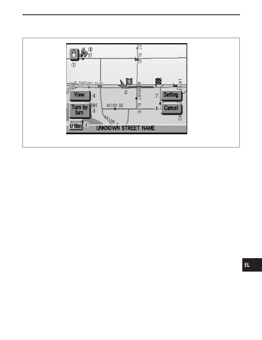
FUNCTION OF TOUCH SWITCH (Summary)
Display with pushed “MAP” switch
SEL580X
The function of each touch switch is as follows:
q
1
Azimuth indication
q
2
Position marker
The tip of the arrow shows the current position. The shaft of
the arrow indicates the direction in which the vehicle is travel-
ing.
q
3
GPS reception signal (indicates current reception conditions)
q
4
Distance display (shows the distance in a reduced scale)
q
5
Current location voice information
(this information is available when the route guide is being
activated and the designated route is being traveled.)
q
6
Switch display from map screen to BIRDVIEW
T
screen
(change to map screen on display when the BIRDVIEW
T
is
being used.)
q
7
The following items can be set.
I
Save Current Location
I
Edit Address Book
I
Guide Volume
I
System Setting
q
8
The route guide operation can be canceled.
GI
MA
EM
LC
EC
FE
AT
PD
FA
RA
BR
ST
RS
BT
HA
IDX
NAVIGATION SYSTEM
System Description (Cont’d)
EL-545
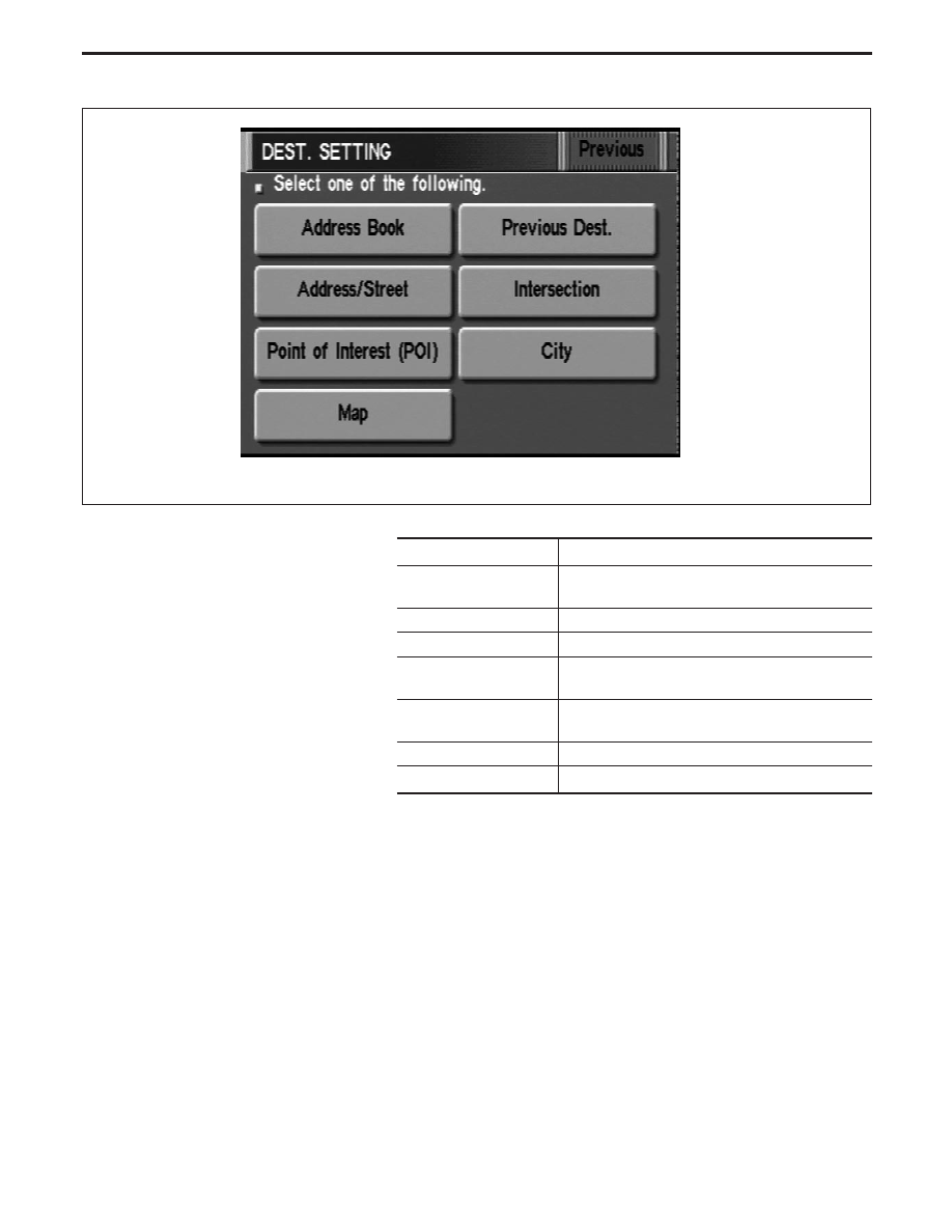
Display with pushed “DEST” switch
SEL581X
The function of each touch switch is as follows:
Icon
Description
Address Book
Favorite place can be saved to memory.
The destination can be selected from the memory.
Address/Street
The destination can be searched from the address.
Point of Interest (POI)
The destination of favorite facility can be searched.
Previous Dest.
The previous ten destinations stored in memory
are displayed.
Intersection
The destination from the intersection name can be
retrieved.
City
The destination can be searched from city name.
Map
The destination can be searched from the map.
NAVIGATION SYSTEM
System Description (Cont’d)
EL-546
Нет комментариевНе стесняйтесь поделиться с нами вашим ценным мнением.
Текст