Infiniti Q45 (FY33). Manual — part 289
Meter/Gauge Operation and Odo/Trip Meter
Segment Check in Diagnosis Mode
DIAGNOSIS FUNCTION
I
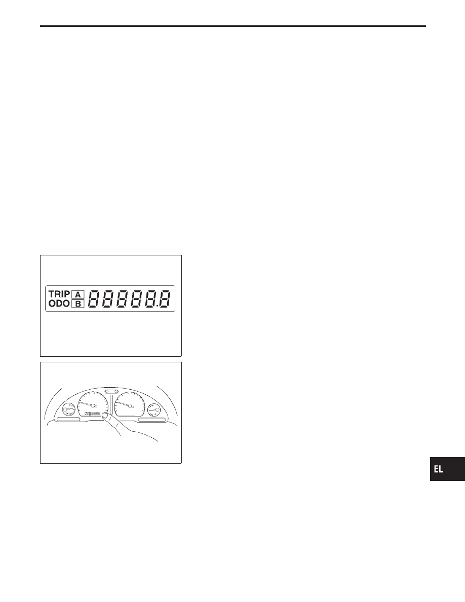
Odo/trip meter segment can be checked in diagnosis mode.
I
Meters/gauges can be checked in diagnosis mode.
HOW TO ALTERNATE DIAGNOSIS MODE
1.
Turn ignition switch to ON and change odo/trip meter to “TRIP
A” or “TRIP B”.
2.
Turn ignition switch to OFF.
3.
Turn ignition switch to ON when pushing odo/trip meter switch.
4.
Confirm that trip meter indicates “000.0”.
5.
Push odo/trip meter switch more than three times within 5
seconds.
SEL110V
6.
All odo/trip meter segments should be turned on.
NOTE: If some segments are not turned on, speedometer (uni-
fied meter control unit) with odo/trip meter should be
replaced.
At this point, the unified control meter is turned to diagnosis
mode.
SEL111V
7.
Push odo/trip meter switch. Indication of each meter/gauge
should be as shown left during pushing odo/trip meter switch
if it is no malfunctioning.
NOTE: It takes about 1 minute for indication of fuel gauge to
become stable.
GI
MA
EM
LC
EC
FE
AT
PD
FA
RA
BR
ST
RS
BT
HA
IDX
METER AND GAUGES
EL-147
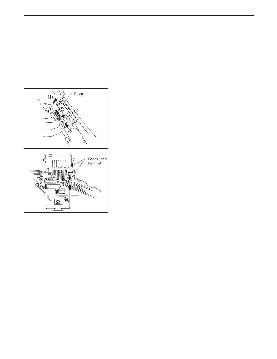
Flexible Print Circuit (FPC)
Tachometer, fuel gauge and water temperature gauge are con-
nected with unified meter control unit (speedometer) by Flexible
Print Circuit (FPC) connector. When replace or remove and install
unified control unit (speedometer), disconnect and connect FPC
connector according to the following steps.
SEL109V
DISCONNECT
1.
Open connector cover.
2.
Release connector lock by holding both ends of it and pulling
it up.
3.
Disconnect FPC by pulling it up.
SEL114V
CONNECT
1.
Insert FPC into connector and lock connector pushing FPC
downward.
2.
Check secure connection of FPC.
3.
Check continuity of check land terminal for secure connection
of FPC.
Resistance: 0
Ω
4.
Close connector cover.
METER AND GAUGES
EL-148
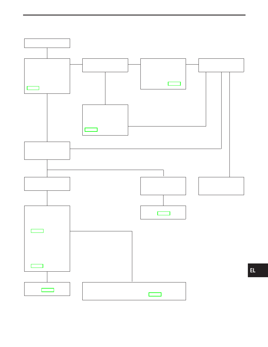
Trouble Diagnoses
PRELIMINARY CHECK
CHECK-IN
Can Diagnosis mode
be activated? Refer to
“Meter/Gauge Opera-
tion and Odo/Trip Meter
Segment Check in
Diagnosis Mode”,
EL-147.
Yes
E
No
Do meter warning
lamps operate?
No
E
Yes
Check the screws
securing speedometer.
(The screws are
located behind the
combination meter. For
details refer to EL-153.)
E
Can Diagnosis mode
be activated?
No
G
Check power supply
and ground circuit.
Refer to “POWER SUP-
PLY AND GROUND
CIRCUIT CHECK”,
EL-150.
Check meter/gauge
operation in Diagnosis
mode.
F
Yes
H
Malfunction is indicated
in Diagnosis mode.
No malfunction is indi-
cated in Diagnosis
mode.
Replace speedometer
(unified meter control
unit).
Check the following:
I
FPC connector con-
nection
Refer to “Flexible
Print Circuit (FPC)”,
EL-148.
I
Screws securing the
malfunctioning meter/
gauge
(The screws are
located behind the
combination meter.
For details refer to
EL-153.)
OK
H
NG
SYMPTOM CHART 2
Refer to EL-150.
SYMPTOM CHART 1
Refer to EL-150.
Reconnect FPC connector and check continuity between
check land terminals and/or repair malfunctioning part.
Refer to “Flexible Print Circuit (FPC)”, EL-148.
GI
MA
EM
LC
EC
FE
AT
PD
FA
RA
BR
ST
RS
BT
HA
IDX
METER AND GAUGES
H
H
H
H
H
H
H
H
EL-149
SYMPTOM CHART
Symptom chart 1 (Malfunction is indicated in Diagnosis mode)
Symptom
Possible causes
Repair order
Speedometer and/or odo/trip
meter indicate(s) malfunction
in Diagnosis mode.
I
Speedometer (Unified meter control unit)
I
Replace speedometer (unified meter control unit).
Multiple meter/gauge indicate
malfunction in Diagnosis
mode.
One of tachometer/fuel gauge/
water temp. gauge indicates
malfunction in Diagnosis
mode.
I
Meter/Gauge
I
Speedometer (Unified meter control unit)
1. Check resistance of meter/gauge indicating malfunction. If
the resistance is NG, replace the meter/gauge. Refer to
“METER/GAUGE RESISTANCE CHECK”, EL-153.
2. If the resistance is OK, replace speedometer (unified meter
control unit).
Symptom chart 2 (No malfunction is indicated in Diagnosis mode)
Symptom
Possible causes
Repair order
Speedometer and odo/trip
meter are malfunctioning.
1. Sensor
- Speedometer, Odo/Trip meter
2. FPC connector
3. Speedometer (Unified meter control unit)
1. Check vehicle speed sensor.
INSPECTION/VEHICLE SPEED SENSOR (Refer to EL-151.)
2. Check FPC connector. Refer to “Flexible Print Circuit (FPC)”,
3. Replace speedometer (unified meter control unit).
Multiple meter/gauge are mal-
functioning. (except
speedometer, odo/trip meter)
1. FPC connector
2. Speedometer (Unified meter control unit)
1. Check FPC connector. Refer to “Flexible Print Circuit (FPC)”,
2. Replace speedometer (unified meter control unit).
One of tachometer/fuel gauge/
water temp. gauge is malfunc-
tioning.
1. Sensor/Engine revolution signal
- Tachometer
- Fuel gauge
- Water temp. gauge
2. FPC connector
3. Speedometer (Unified meter control unit)
1. Check the sensor for malfunctioning meter/gauge.
INSPECTION/ENGINE REVOLUTION SIGNAL (Refer to
EL-152.)
INSPECTION/FUEL LEVEL SENSOR UNIT (Refer to
EL-152.)
INSPECTION/THERMAL TRANSMITTER (Refer to EL-153.)
2. Check FPC connector. Refer to “Flexible Print Circuit (FPC)”,
3. Replace speedometer (unified meter control unit).
Before starting trouble diagnoses above, perform PRELIMINARY CHECK, EL-149.
SEL367VA
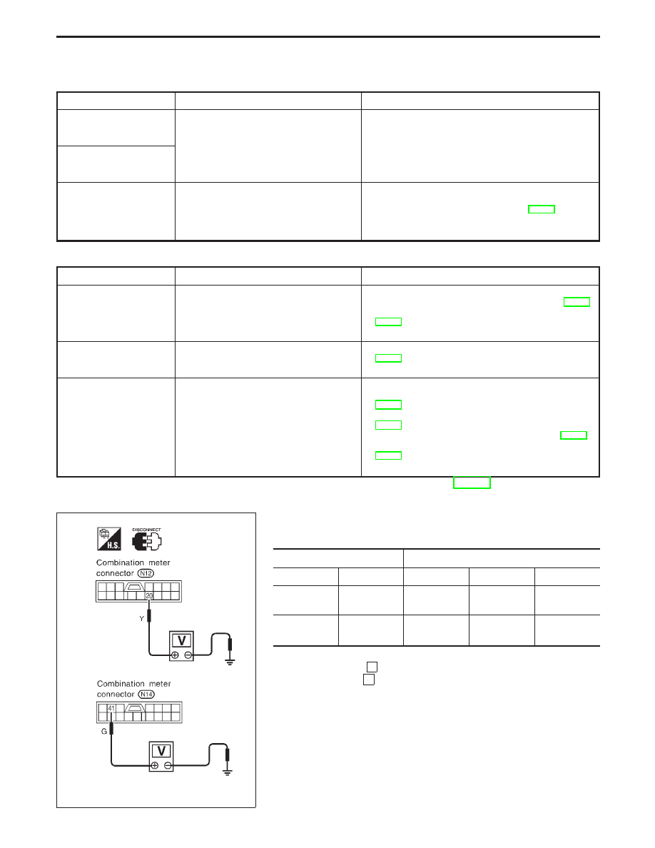
POWER SUPPLY AND GROUND CIRCUIT CHECK
Power supply circuit check
Terminals
Ignition switch position
!
@
OFF
ACC
ON
q
20
Ground
Battery
voltage
Battery
voltage
Battery
voltage
q
41
Ground
0V
0V
Battery
voltage
If NG, check the following.
I
7.5A fuse [No.
4
, located in fuse block (J/B)]
I
10A fuse [No.
28
, located in fuse block (J/B)]
I
Harness for open or short between fuse and combination
meter
METER AND GAUGES
Trouble Diagnoses (Cont’d)
EL-150
Нет комментариевНе стесняйтесь поделиться с нами вашим ценным мнением.
Текст