Infiniti Q45 (FY33). Manual — part 166
SEF054TI
SEF056TH
SEF409WA
SEF390UA
q
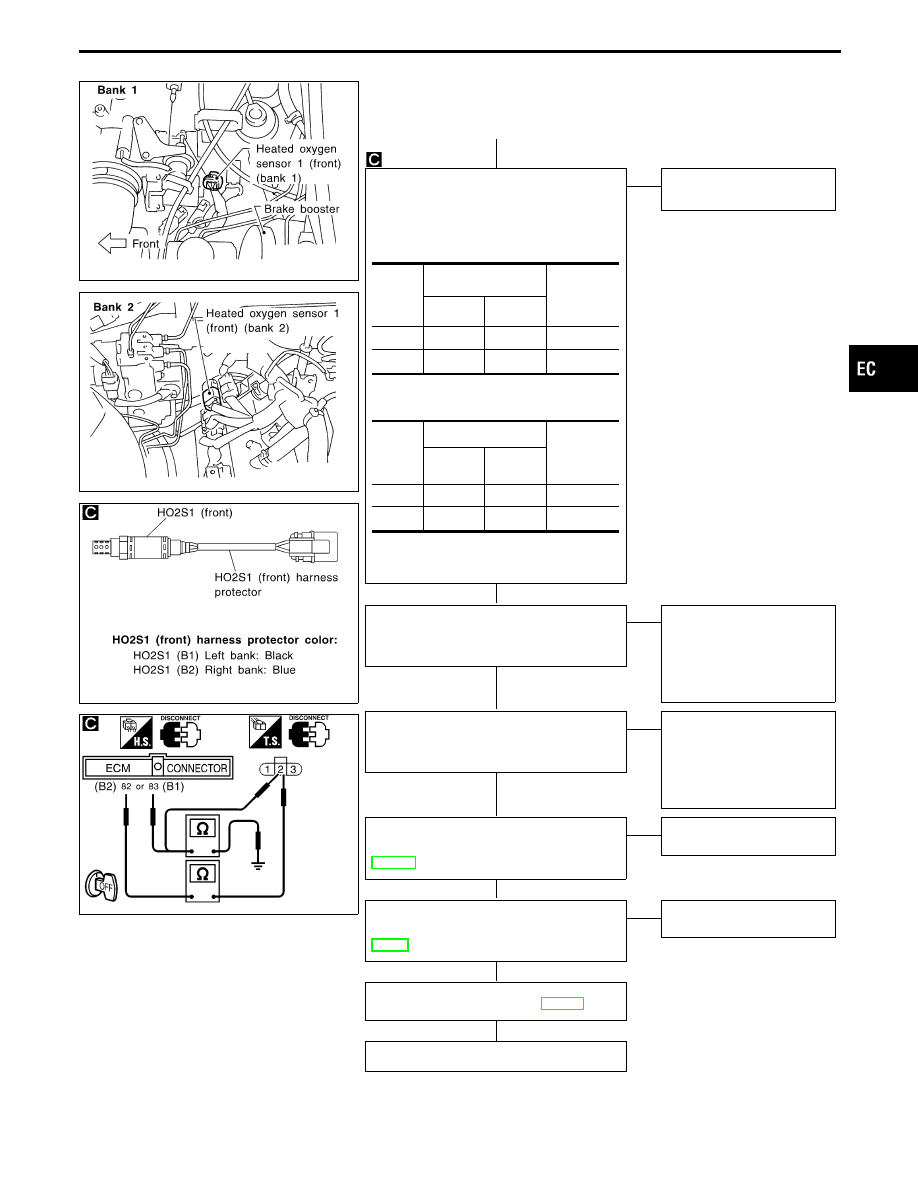
A
CHECK INPUT SIGNAL CIRCUIT.
1. Turn ignition switch “OFF”.
2. Disconnect corresponding heated oxy-
gen sensor 1 (front) harness connector
and ECM harness connector.
3. Check harness continuity between ECM
and sensor terminals.
Continuity should exist.
4. Check harness continuity between ECM
and sensor or ground.
Continuity should not exist.
If OK, check harness for short to
ground and short to power.
OK
E
NG
Repair harness or connec-
tors.
CHECK COMPONENT
[Heated oxygen sensor 1 heater (front)].
Refer to “COMPONENT INSPECTION” on
next page.
OK
E
NG
REPLACE HO2S1 (front).
1. Check HO2S1 (front)
harness protector color.
Black: Left bank (B1)
Blue: Right bank (B2)
2. Replace malfunctioning
HO2S1 (front)
CHECK COMPONENT
[Heated oxygen sensor 1 (front)].
Refer to “COMPONENT INSPECTION” on
next page.
OK
E
NG
REPLACE HO2S1 (front).
1. Check HO2S1 (front)
harness protector color.
Black: Left bank (B1)
Blue: Right bank (B2)
2. Replace malfunctioning
HO2S1 (front)
CHECK COMPONENT
(Mass air flow sensor).
Refer to “COMPONENT INSPECTION”,
EC-131.
OK
E
NG
Replace mass air flow sen-
sor.
CHECK COMPONENT
(PCV valve).
Refer to “COMPONENT INSPECTION”,
EC-36.
OK
E
NG
Repair or replace PCV
valve.
Perform “TROUBLE DIAGNOSIS FOR
INTERMITTENT INCIDENT”, EC-117.
OK
INSPECTION END
DTC
Terminals
Bank
(Harness
protector
color)
ECM
Sensor
P0133
83
2
B1 (Black)
P0153
82
2
B2 (Blue)
DTC
Terminals
Bank
(Harness
protector
color)
ECM or
sensor
Ground
P0133
83 or 2
Ground
B1 (Black)
P0153
82 or 2
Ground
B2 (Blue)
GI
MA
EM
LC
FE
AT
PD
FA
RA
BR
ST
RS
BT
HA
EL
IDX
TROUBLE DIAGNOSIS FOR DTC P0133 (B1), P0153 (B2)
Heated Oxygen Sensor 1 (Front) (P0133: Bank
1), (P0153: Bank 2) (Response monitoring)
(Cont’d)
H
H
H
H
H
H
H
EC-193
AEC158A
COMPONENT INSPECTION
Heated oxygen sensor 1 heater (front)
Check resistance between terminals
q
3
and
q
1
.
Resistance: 2.3 - 4.3
Ω
at 25°C (77°F)
Check continuity between terminals
q
2
and
q
1
,
q
3
and
q
2
.
Continuity should not exist.
If NG, replace the heated oxygen sensor 1 (front).
CAUTION:
I
Discard any heated oxygen sensor which has been
dropped from a height of more than 0.5 m (19.7 in) onto a
hard surface such as a concrete floor; use a new one.
I
Before installing new oxygen sensor, clean exhaust sys-
tem threads using Oxygen Sensor Thread Cleaner tool
J-43897-18 or J-43897-12 and approved anti-seize lubri-
cant.
SEF977Z
Heated oxygen sensor 1 (front)
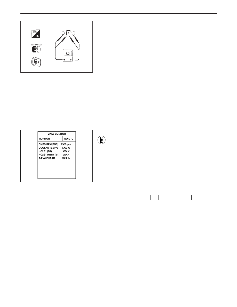
1) Start engine and warm it up to normal operating tem-
perature.
2) Select “MANU TRIG” and “HI SPEED” in “DATA MONI-
TOR” mode with CONSULT-II, and select “HO2S1 (B1)
(B2)” and “HO2S1 MNTR (B1) (B2)”.
3) Hold engine speed at 2,000 rpm under no load during
the following steps.
4) Touch “RECORD” on CONSULT-II screen.
5) Check the following.
I
“HO2S1 MNTR (B1) (B2)” in “DATA MONITOR” mode
changes from “RICH” to “LEAN” to “RICH” 5 times in 10
seconds.
5 times (cycles) are counted as shown below:
cycle
1
2
3
4
5
HO2S1 MNTR (B1) R-L-R-L-R-L-R-L-R-L-R
R = “HO2S1 MNTR (B1) (B2)”, “RICH”
L = “HO2S1 MNTR (B1) (B2)”, “LEAN”
I
“HO2S1 (B1) (B2)” voltage goes above 0.6V at least
once.
I
“HO2S1 (B1) (B2)” voltage goes below 0.30V at least
once.
I
The voltage never exceeds 1.0V.
CAUTION:
I
Discard any heated oxygen sensor which has been
dropped from a height of more than 0.5 m (19.7 in) onto a
hard surface such as a concrete floor; use a new one.
I
Before installing new oxygen sensor, clean exhaust sys-
tem threads using Oxygen Sensor Thread Cleaner tool
J-43897-18 or J-43897-12 and approved anti-seize lubri-
cant.
TROUBLE DIAGNOSIS FOR DTC P0133 (B1), P0153 (B2)
Heated Oxygen Sensor 1 (Front) (P0133: Bank
1), (P0153: Bank 2) (Response monitoring)
(Cont’d)
EC-194
SEF978Z
SEF353WA
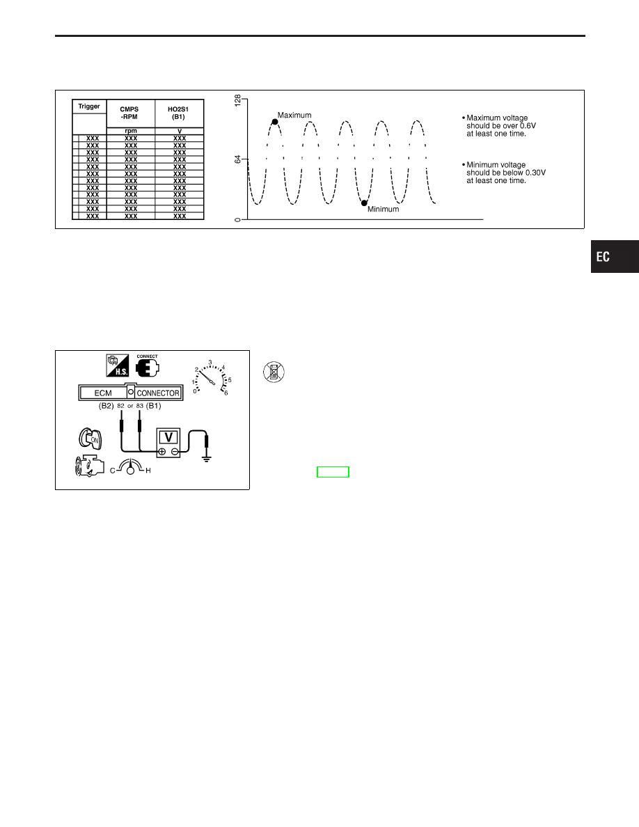
------------------------------------------------------------------------------------------------------------------------------------------------------------------------------------------------------------------------------------------------------ OR ------------------------------------------------------------------------------------------------------------------------------------------------------------------------------------------------------------------------------------------------------
1) Start engine and warm it up to normal operating tem-
perature.
2) Set voltmeter probes between ECM terminal
q
82
(B2),
q
83
(B1) (sensor signal) and ground.
3) Check the following with engine speed held at 2,000
rpm constant under no load.
I
Malfunction indicator lamp goes on more than 5 times
within 10 seconds in Diagnostic Test Mode II [HEATED
OXYGEN SENSOR 1 MONITOR (FRONT)]. See
EC-68.
I
The maximum voltage is over 0.6V at least one time.
I
The minimum voltage is below 0.30V at least one time.
I
The voltage never exceeds 1.0V.
CAUTION:
I
Discard any heated oxygen sensor which has been
dropped from a height of more than 0.5 m (19.7 in) onto a
hard surface such as a concrete floor; use a new one.
I
Before installing new oxygen sensor, clean exhaust sys-
tem threads using Oxygen Sensor Thread Cleaner tool
J-43897-18 or J-43897-12 and approved anti-seize lubri-
cant.
GI
MA
EM
LC
FE
AT
PD
FA
RA
BR
ST
RS
BT
HA
EL
IDX
TROUBLE DIAGNOSIS FOR DTC P0133 (B1), P0153 (B2)
Heated Oxygen Sensor 1 (Front) (P0133: Bank
1), (P0153: Bank 2) (Response monitoring)
(Cont’d)
EC-195
SEF463R
Heated Oxygen Sensor 1 (Front) (P0134: Bank
1), (P0154: Bank 2)
SEF288D
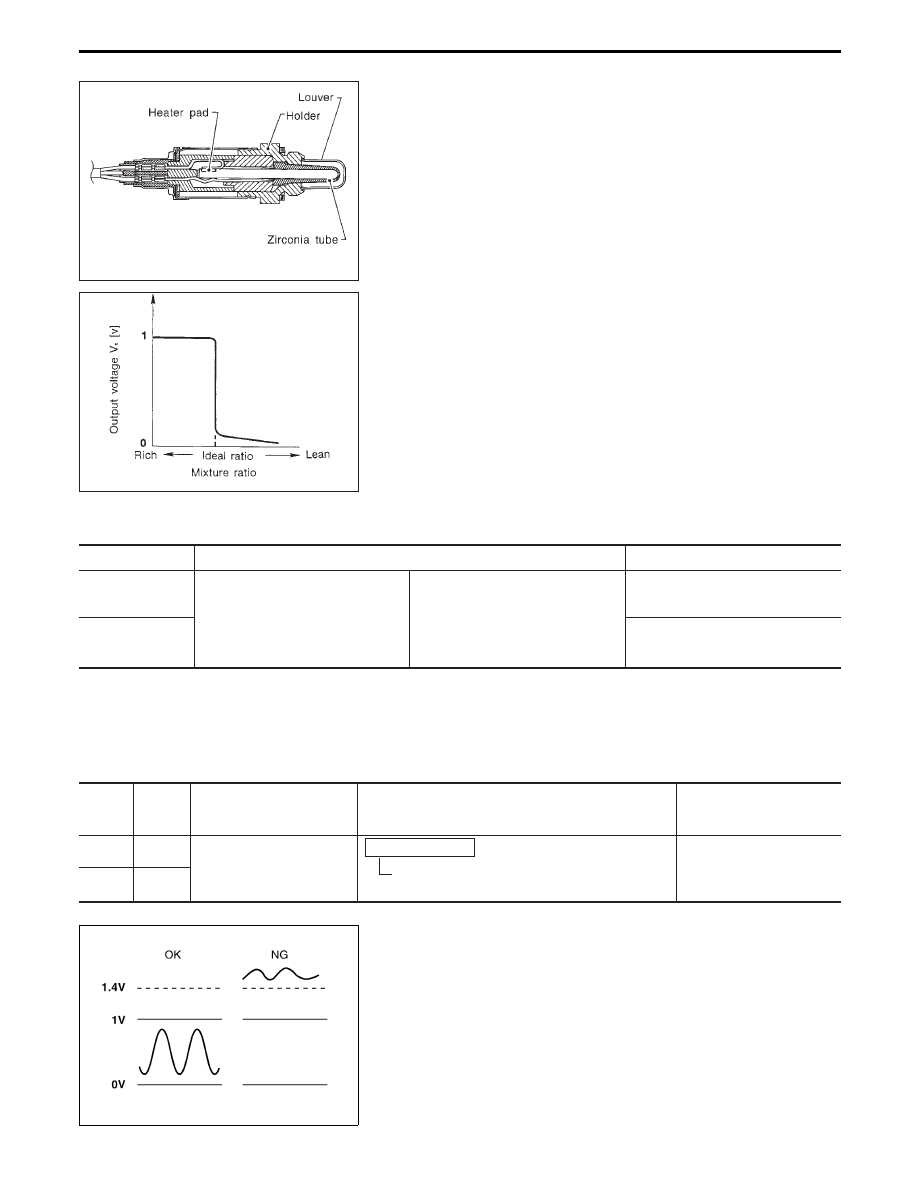
COMPONENT DESCRIPTION
The heated oxygen sensor 1 (front) is placed into the exhaust
manifold. It detects the amount of oxygen in the exhaust gas com-
pared to the outside air. The heated oxygen sensor 1 (front) has a
closed-end tube made of ceramic zirconia. The zirconia generates
voltage from approximately 1V in richer conditions to 0V in leaner
conditions. The heated oxygen sensor 1 (front) signal is sent to the
ECM. The ECM adjusts the injection pulse duration to achieve the
ideal air-fuel ratio. The ideal air-fuel ratio occurs near the radical
change from 1V to 0V.
CONSULT-II REFERENCE VALUE IN DATA MONITOR MODE
Specification data are reference values.
MONITOR ITEM
CONDITION
SPECIFICATION
HO2S1 (B1)
HO2S1 (B2)
I
Engine: After warming up
Maintaining engine speed at 2,000 rpm
0 - 0.3V
)
0.6 - 1.0V
HO2S1 MNTR (B1)
HO2S1 MNTR (B2)
LEAN
)
RICH
Changes more than 5 times
during 10 seconds.
ECM TERMINALS AND REFERENCE VALUE
Specification data are reference values, and are measured between each terminal and ground.
CAUTION:
Do not use ECM ground terminals when measuring voltage. Doing so may result in damage to the
ECM’s transistor. Use a ground other than ECM terminals such as the body ground.
TER-
MINAL
NO.
WIRE
COLOR
ITEM
CONDITION
DATA
(DC voltage)
82 (B2)
R
Heated oxygen sensor 1
(front)
Engine is running.
After warming up to normal operating tempera-
ture and engine speed is 2,000 rpm.
0 - Approximately 1.0V
(periodically change)
83 (B1)
W
SEF301UA
ON BOARD DIAGNOSIS LOGIC
To judge the malfunction, the diagnosis checks that the heated
oxygen sensor 1 (front) output is not inordinately high.
TROUBLE DIAGNOSIS FOR DTC P0134 (B1), P0154 (B2)
EC-196
Нет комментариевНе стесняйтесь поделиться с нами вашим ценным мнением.
Текст