Infiniti Q45 (FY33). Manual — part 20
SAT010C
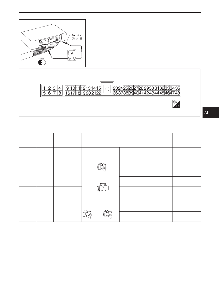
TCM Terminals and Reference Value
PREPARATION
I
Measure voltage between each terminal and terminal
q
15
or
q
48
by following “TCM INSPECTION TABLE”.
TCM HARNESS CONNECTOR TERMINAL LAYOUT
SAT207I
TCM INSPECTION TABLE
(Data are reference values.)
Terminal
No.
Wire color
Item
Condition
Judgement
standard
(Approx.)
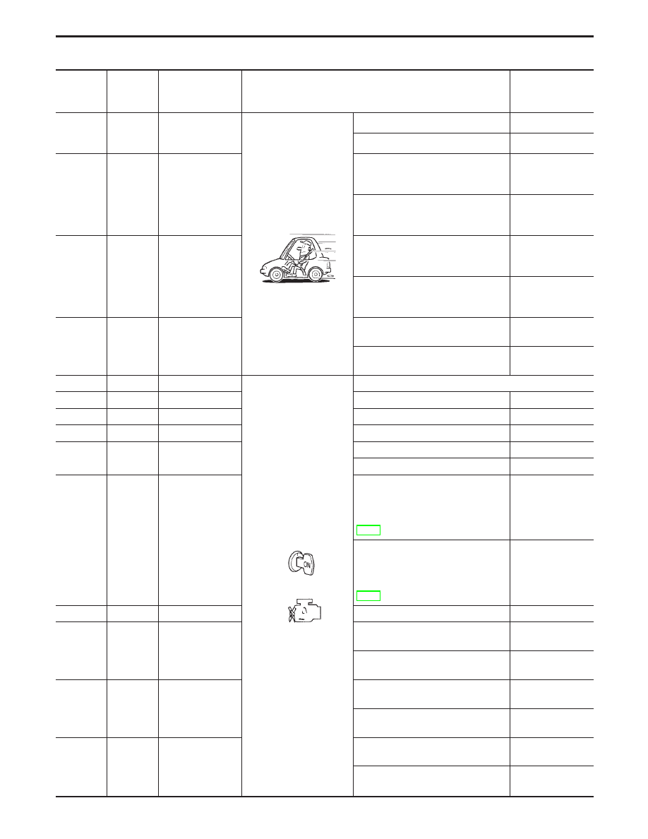
1
G/R
Line pressure
solenoid valve
When releasing accelerator pedal
after warming up engine.
1.5 - 2.5V
When depressing accelerator pedal
fully after warming up engine.
0V
2
W/B
Line pressure
solenoid valve
(with dropping
resistor)
When releasing accelerator pedal
after warming up engine.
5 - 14V
When depressing accelerator pedal
fully after warming up engine.
0V
3
G/Y
O/D OFF indicator
lamp
When setting overdrive control
switch in “OFF” position.
0V
When setting overdrive control
switch in “ON” position.
Battery voltage
4
G/B
Power source
or
When turning ignition switch to “ON”. Battery voltage
When turning ignition switch to
“OFF”.
0V
GI
MA
EM
LC
EC
FE
PD
FA
RA
BR
ST
RS
BT
HA
EL
IDX
TROUBLE DIAGNOSIS — General Description
AT-77
Terminal
No.
Wire color
Item
Condition
Judgement
standard
(Approx.)
5
G/B
Torque converter
clutch solenoid
valve
When A/T performs lock-up.
8 - 15V
When A/T does not perform lock-up.
0V
6
R/Y
Shift solenoid
valve A
When shift solenoid valve A oper-
ates.
(When driving in “D
1
” or “D
4
”.)
Battery voltage
When shift solenoid valve A does not
operate.
(When driving in “D
2
” or “D
3
”.)
0V
7
LG/B
Shift solenoid
valve B
When shift solenoid valve B oper-
ates.
(When driving in “D
1
” or “D
2
”.)
Battery voltage
When shift solenoid valve B does
not operate.
(When driving in “D
3
” or “D
4
”.)
0V
8
L
Overrun clutch
solenoid valve
When overrun clutch solenoid valve
operates.
Battery voltage
When overrun clutch solenoid valve
does not operate.
0V
9
G/B
Power source
Same as No. 4
10
—
—
—
—
11
—
—
—
—
12
—
—
—
—
13
—
—
—
—
—
—
14
GY/L
Closed throttle
position switch
(in throttle position
switch)
When releasing accelerator pedal
after warming up engine. (Refer to
“Preparation”, “TCM SELF-DIAG-
NOSTIC PROCEDURE (No Tools)”,
AT-49.)
Battery voltage
When depressing accelerator pedal
after warming up engine. (Refer to
“Preparation”, “TCM SELF-DIAG-
NOSTIC PROCEDURE (No Tools)”,
AT-49.)
0V
15
B
Ground
—
—
16
PU/W
PNP switch “1”
position
When setting selector lever to “1”
position.
Battery voltage
When setting selector lever to other
positions.
0V
17
P/B
PNP switch “2”
position
When setting selector lever to “2”
position.
Battery voltage
When setting selector lever to other
positions.
0V
18
Y/PU
PNP switch “D”
position
When setting selector lever to “D”
position.
Battery voltage
When setting selector lever to other
positions.
0V
TROUBLE DIAGNOSIS — General Description
TCM Terminals and Reference Value (Cont’d)
AT-78

Terminal
No.
Wire color
Item
Condition
Judgement
standard
(Approx.)
19
R/G
PNP switch “N” or
“P” position
When setting selector lever to “N” or
“P” position.
Battery voltage
When setting selector lever to other
positions.
0V
20
L/W
PNP switch “R”
position
When setting selector lever to “R”
position.
Battery voltage
When setting selector lever to other
positions.
0V
21
W/R
Wide open throttle
position switch
(in throttle position
switch)
When depressing accelerator pedal
more than half-way after warming up
engine.
Battery voltage
When releasing accelerator pedal
after warming up engine.
0V
22
—
—
—
—
23
Y
Power source
(Memory back-up)
or
When turning ignition switch to
“OFF”.
Battery voltage
When turning ignition switch to “ON”. Battery voltage
24
W/G
Engine speed sig-
nal
When engine runs at idle speed.
1.2V
When engine runs at 3,000 rpm.
3.4V
25
W
Revolution sensor
(Measure in AC
range)
When vehicle cruises at 30 km/h (19
MPH).
1V or more
Voltage rises
gradually in
response to
vehicle speed.
When vehicle parks.
0V
26
Y
Turbine revolution
sensor
(Measure in AC
range)
When engine is running at 1,000
rpm
1.2V
Voltage rises
gradually in
response to
engine speed.
27
P/L
Vehicle speed sen-
sor
When moving vehicle at 2 to 3 km/h
(1 to 2 MPH) for 1 m (3 ft) or more.
Voltage varies
between less than
1V and more than
4.5V
28*
BR/Y
—
—
—
29
—
—
—
—
30*
P
—
—
—
31
BR/W
Throttle position
sensor
(Power source)
Ignition switch: ON
4.5 - 5.5V
Ignition switch: OFF
0V
32
—
—
—
—
*: These terminals are connected to the Data link connector.
GI
MA
EM
LC
EC
FE
PD
FA
RA
BR
ST
RS
BT
HA
EL
IDX
TROUBLE DIAGNOSIS — General Description
TCM Terminals and Reference Value (Cont’d)
AT-79
Terminal
No.
Wire color
Item
Condition
Judgement
standard
(Approx.)
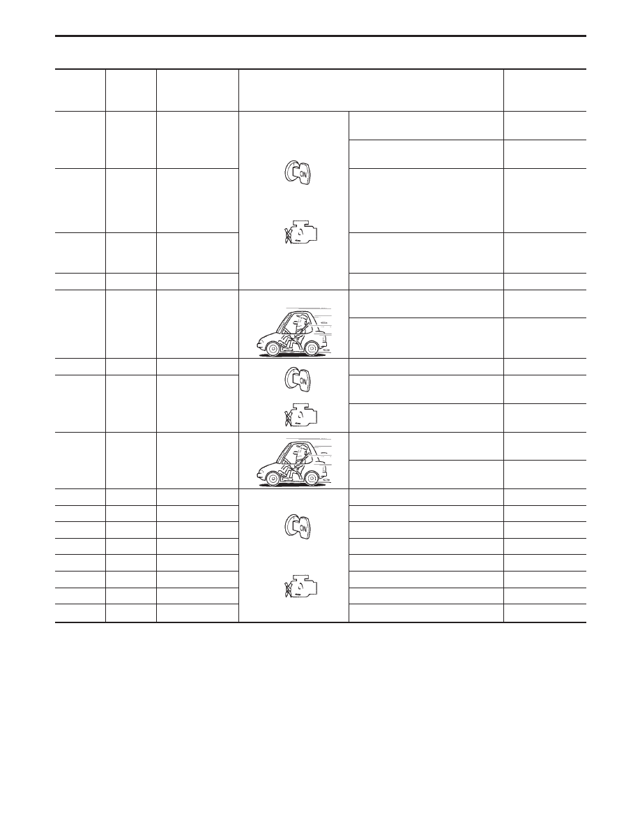
33
G
A/T fluid tempera-
ture sensor
When ATF temperature is 20°C
(68°F).
1.5V
When ATF temperature is 80°C
(176°F).
0.5V
34
L/B
Throttle position
sensor
When depressing accelerator pedal
slowly after warming up engine.
(Voltage rises gradually in response
to throttle position.)
Fully-closed
throttle:
0.5V
Fully-open throttle:
4V
35
B
Throttle position
sensor
(Ground)
—
—
36
—
—
—
—
37
Y
ASCD cruise sig-
nal
When ASCD cruise is being per-
formed. (“CRUISE” light comes on.)
Battery voltage
When ASCD cruise is not being per-
formed. (“CRUISE” light does not
comes on.)
0V
38
—
—
—
—
39
G/Y
Overdrive control
switch
When setting overdrive control
switch in “ON” position
Battery voltage
When setting overdrive control
switch in “OFF” position
0V
40
L
ASCD OD cut sig-
nal
When “ACCEL” set switch on ASCD
cruise is released.
5 - 8V
When “ACCEL” set switch on ASCD
cruise is applied.
0V
41
—
—
—
—
42
—
—
—
—
43
—
—
—
—
44
—
—
—
—
45
—
—
—
—
46
—
—
—
—
47*
R/L
LAN
—
—
48
B
Ground
—
—
* This terminal is connected to the ECM.
TROUBLE DIAGNOSIS — General Description
TCM Terminals and Reference Value (Cont’d)
AT-80
Нет комментариевНе стесняйтесь поделиться с нами вашим ценным мнением.
Текст