Infiniti Q45 (FY33). Manual — part 50

SAT133B
5.
Remove rear extension from transmission case.
6.
Replace parking pawl components if necessary.
7.
Reinstall any part removed.
I
Always use new sealing parts.
SAT062J
Park/Neutral Position (PNP) Switch Adjustment
1.
Remove manual control linkage from manual shaft of A/T
assembly.
2.
Set manual shaft of A/T assembly in “N” position.
3.
Loosen PNP switch fixing bolts.
SAT063J
4.
Insert pin into adjustment holes in both PNP switch and
manual shaft of A/T assembly as near vertical as possible.
5.
Reinstall any part removed.
6.
Check continuity of PNP switch. Refer to “Component
Inspection”, AT-84.
SAT617I
Manual Control Linkage Adjustment
Move selector lever from “P” position to “1” position. You should be
able to feel the detents in each position.
If the detents cannot be felt or the position pointer is improperly
aligned, adjust the linkage.
1.
Place selector lever in “P” position.
2.
Loosen lock nuts.
SAT578I
3.
Place manual shaft in “P” position.
4.
Tighten lock nut to the specified torque.
Lock nut:
: 18 - 23 N
⋅
m (1.8 - 2.3 kg-m, 13 - 17 ft-lb)
5.
Move selector lever from “P” position to “1” position. Make sure
that selector lever can move smoothly.
GI
MA
EM
LC
EC
FE
PD
FA
RA
BR
ST
RS
BT
HA
EL
IDX
ON-VEHICLE SERVICE
Parking Pawl Components Inspection (Cont’d)
AT-197

Removal
SAT618IA
SAT615IA
CAUTION:
When removing the A/T assembly from engine, first remove
the crankshaft position sensor (OBD) from the assembly.
Be careful not to damage sensor edge.
1.
Remove battery negative terminal.
2.
Remove crankshaft position sensor (OBD) from A/T assembly.
3.
Remove rear heated oxygen sensor harness connector.
4.
Remove exhaust tube, muffler and heat insulator. Refer to FE
section (“EXHAUST SYSTEM”).
5.
Remove fluid charging pipe from A/T assembly.
6.
Remove oil cooler pipe clamps.
7.
Remove oil cooler pipe from A/T assembly.
8.
Plug up openings such as the oil charging pipe hole, etc.
9.
Disconnect A/T harness connectors.
10. Remove control linkage from selector lever.
11. Remove propeller shaft. Refer to PD section (“Removal”,
“PROPELLER SHAFT”).
I
Insert plug into rear oil seal after removing propeller shaft.
I
Be careful not to damage spline, sleeve yoke and rear oil
seal, when removing propeller shaft.
REMOVAL AND INSTALLATION
AT-198
SAT619I
12. Remove rear cover plate and bolts securing torque converter
to drive plate. Tighten rear plate cover bolts to the specified
torque. Refer to EM section (“OIL PAN”).
13. Remove engine under cover.
I
Remove the bolts by turning crankshaft.
SAT620I
14. Support A/T assembly by placing a jack under oil pan.
15. Remove rear engine mounting member from body. Tighten
rear engine mounting member bolts to the specified torque.
Refer to EM section (“ENGINE REMOVAL”).
16. Remove bolts securing A/T assembly to engine.
17. Lower A/T assembly.
SAT977H
Installation
1.
Check drive plate runout.
CAUTION:
Do not allow any magnetic materials to contact the ring gear
teeth.
Maximum allowable runout:
Refer to EM section (“Inspection”, “CYLINDER
BLOCK”).
I
If this runout is out of specification, replace drive plate with ring
gear.
SAT017B
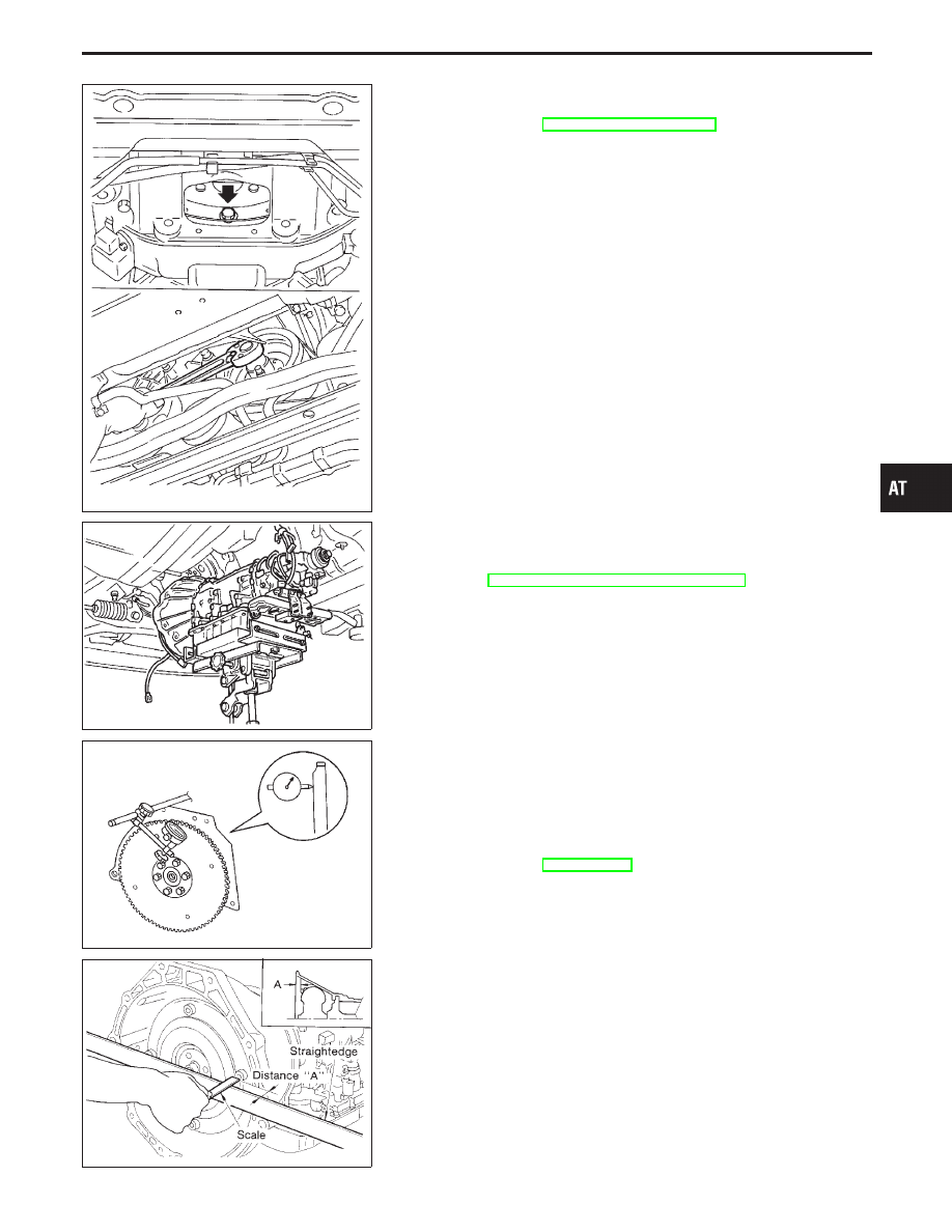
2.
When connecting torque converter to transmission, measure
distance “A” to be certain that they are correctly assembled.
Distance “A”:
22.0 mm (0.866 in) or more
GI
MA
EM
LC
EC
FE
PD
FA
RA
BR
ST
RS
BT
HA
EL
IDX
REMOVAL AND INSTALLATION
Removal (Cont’d)
AT-199
SAT621I
3.
Install bolts securing converter to drive plate.
I
After installing converter to drive plate, rotate crankshaft
several turns. Make sure that transmission rotates freely
without binding.
SAT622I
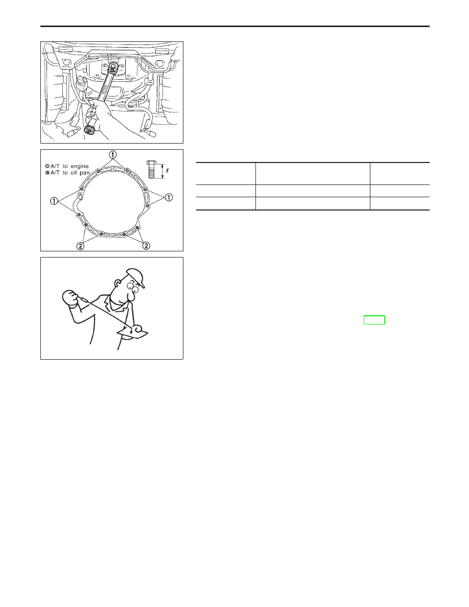
4.
Tighten bolts securing transmission to engine.
Bolt No.
Tightening torque
N
⋅
m (kg-m, ft-lb)
Bolt length “
”
mm (in)
q
1
108 - 118 (11.0 - 12.0, 80 - 87)
70 (2.76)
q
2
69 - 78 (7.0 - 8.0, 51 - 58)
90 (3.54)
5.
Reinstall any part removed.
SAT638A
6.
Check fluid level in transmission.
7.
Move selector lever through all positions to be sure that trans-
mission operates correctly.
With parking brake applied, rotate engine at idling. Move selec-
tor lever thorough “N” to “D”, to “2”, to “1” and to “R”. A slight
shock should be felt by hand gripping selector each time trans-
mission is shifted.
8.
Perform road test. Refer to “ROAD TEST”, AT-64.
REMOVAL AND INSTALLATION
Installation (Cont’d)
AT-200
Нет комментариевНе стесняйтесь поделиться с нами вашим ценным мнением.
Текст