Infiniti Q45 (FY33). Manual — part 516
SRA776A
GI
MA
EM
LC
EC
FE
AT
PD
FA
BR
ST
RS
BT
HA
EL
IDX
REAR SUSPENSION SYSTEM
RA-5
SRA525A
Rear Axle and Rear Suspension Parts
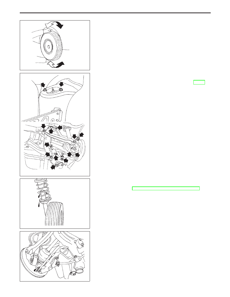
Check axle and suspension parts for excessive play, wear or dam-
age.
I
Shake each rear wheel to check for excessive play.
SRA299A
I
Retighten all nuts and bolts to the specified torque.
Tightening torque:
Refer to drawing in REAR SUSPENSION (RA-19).
I
Make sure that cotter pin is inserted.
SMA113
I
Check shock absorber for oil leakage or other damage.
I
Check wheelarch height. Refer to Front Axle and Front Sus-
pension Parts of ON-VEHICLE SERVICE in FA section.
SRA307A
I
Check suspension ball joint for grease leakage and ball joint
dust cover for cracks or other damage.
ON-VEHICLE SERVICE
RA-6
SRA308A
Rear Wheel Bearing
I
Check wheel bearings for smooth operation.
I
Check axial end play.
Axial end play:
0.05 mm (0.0020 in) or less
If axial end play is not within specification or wheel bearing does
not turn smoothly, replace wheel bearing assembly.
Refer to Wheel Hub and Axle Housing in REAR AXLE (RA-10).
SFA975B
Rear Wheel Alignment
Before checking rear wheel alignment, be sure to make a prelimi-
nary inspection.
PRELIMINARY INSPECTION
1.
Check tires for wear and improper inflation.
2.
Check wheels for deformation, cracks and other damage. If
deformed, remove wheel and check wheel runout.
a.
Remove tire from wheel and mount on wheel a tire balance
machine.
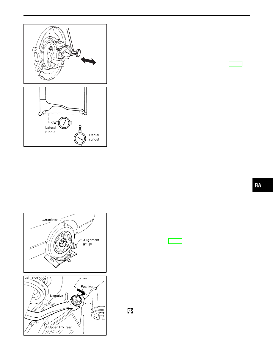
b.
Set dial indicator as shown in the illustration.
Wheel runout (Dial indicator value):
Refer to SDS.
3.
Check front wheel bearings for looseness.
4.
Check front suspension for looseness.
5.
Check steering linkage for looseness.
6.
Check that front shock absorbers work properly.
7.
Check vehicle posture (Unladen).
SRA096A
CAMBER
I
Measure camber of both right and left wheels with a suit-
able alignment gauge and adjust in accordance with the
following procedures.
Camber:
Refer to SDS (RA-26).
SRA311A
If camber is not within specification, adjust by turning the adjusting
bolt.
a.
Turn the adjusting bolt to adjust.
Camber changes about 5
′
with each graduation of the
adjusting bolt.
b.
Tighten to the specified torque.
: 69 - 88 N
⋅
m
(7.0 - 9.0 kg-m, 51 - 65 ft-lb)
GI
MA
EM
LC
EC
FE
AT
PD
FA
BR
ST
RS
BT
HA
EL
IDX
ON-VEHICLE SERVICE
RA-7
SFA614B
SFA234AC
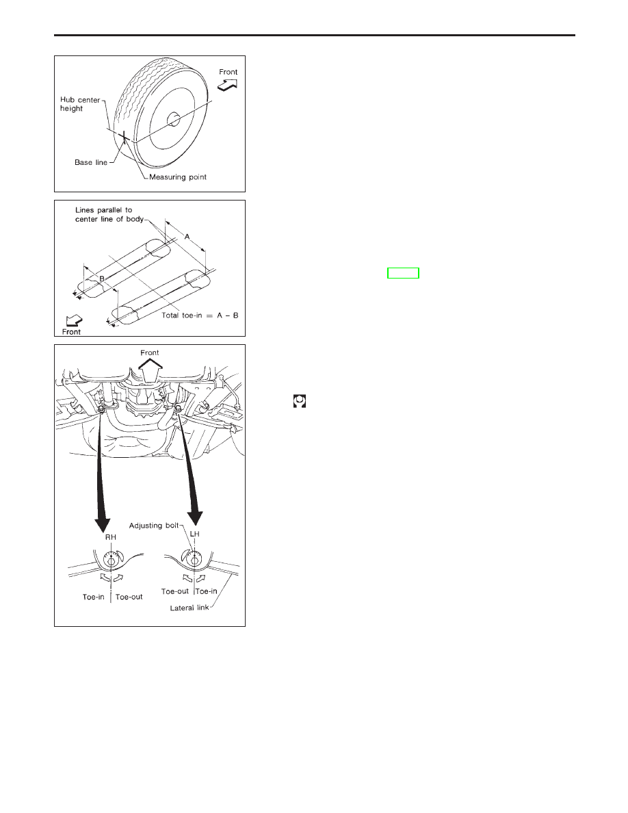
TOE-IN
Measure toe-in using following procedure. If out of specification,
inspect and replace any damaged or worn rear suspension parts.
WARNING:
I
Always perform following procedure on a flat surface.
I
Make sure that no person is in front of the vehicle before
pushing it.
1.
Bounce rear of vehicle up and down to stabilize the posture.
2.
Push the vehicle straight ahead about 5 m (16 ft).
3.
Put a mark on base line of the tread (rear side) of both tires at
the same height of hub center. This mark is a measuring point.
4.
Measure distance “A” (rear side).
5.
Push the vehicle slowly ahead to rotate the wheels 180
degrees (1/2 turn).
If the wheels have rotated more than 180 degrees (1/2 turn), try
the above procedure again from the beginning. Never push
vehicle backward.
6.
Measure distance “B” (front side).
Total toe-in:
Refer to SDS (RA-26).
SRA716A
7.
Adjust toe-in by turning adjusting bolts.
Toe changes about 1.5 mm (0.059 in) [One side] with each
graduation of the adjusting bolt.
8.
Tighten to the specified torque.
: 69 - 88 N
⋅
m
(7.0 - 9.0 kg-m, 51 - 65 ft-lb)
Drive Shaft
Check boot and drive shaft for cracks, wear, damage or grease
leakage.
ON-VEHICLE SERVICE
Rear Wheel Alignment (Cont’d)
RA-8
Нет комментариевНе стесняйтесь поделиться с нами вашим ценным мнением.
Текст