Infiniti Q45 (FY33). Manual — part 242
SEF146TA
SEF147T
SEF796W
SEF797W
SEF814Q
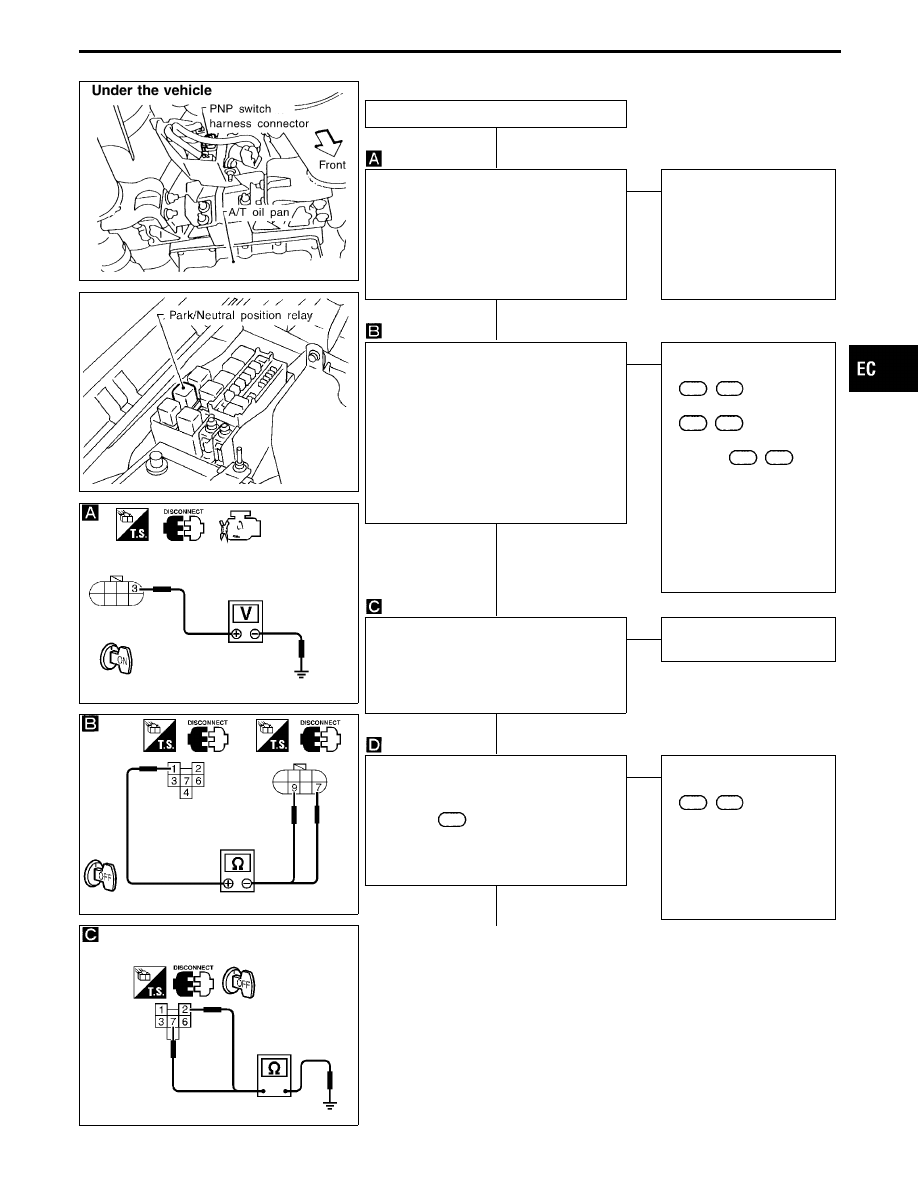
DIAGNOSTIC PROCEDURE
INSPECTION START
CHECK POWER SUPPLY.
1. Disconnect PNP switch harness con-
nector.
2. Turn ignition switch “ON”.
3. Check voltage between terminal
q
3
and
ground with CONSULT-II or tester.
Voltage: Battery voltage
OK
E
NG
Check the following.
I
10A fuse
I
Harness for open or short
between PNP switch and
fuse
If NG, repair harness or
connectors.
CHECK OUTPUT SIGNAL CIRCUIT-I.
1. Turn ignition switch “OFF”.
2. Disconnect park/neutral position relay
harness connector.
3. Check harness continuity between relay
terminal
q
1
and PNP switch terminals
q
7
,
q
9
.
Continuity should exist.
If OK, check harness for short to ground
and short to power.
OK
E
NG
Check the following.
I
Harness connectors
E66
,
M12
I
Harness connectors
M4
,
B3
I
Harness connectors
(diodes)
B10
,
B11
I
Harness for open or short
between PNP switch and
relay
If NG, repair open circuit or
short to ground or short to
power in harness or con-
nectors.
CHECK GROUND CIRCUIT.
1. Check harness continuity between relay
terminals
q
2
,
q
7
and engine ground.
Continuity should exist.
If OK, check harness for short to power.
OK
E
NG
Repair harness or connec-
tors.
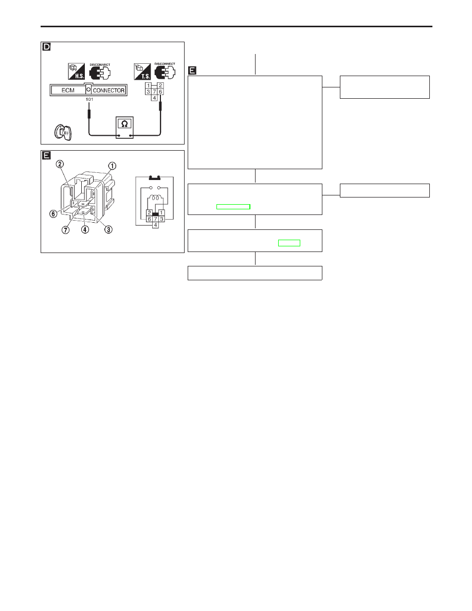
CHECK OUTPUT SIGNAL CIRCUIT-II.
1. Disconnect ECM harness connector.
2. Check harness continuity between ECM
terminal
101
and relay terminal
q
6
.
Continuity should exist.
If OK, check harness for short to ground
and short to power.
OK
E
NG
Check the following.
I
Harness connectors
E13
,
F2
I
Harness for open or short
between ECM and relay
If NG, repair open circuit or
short to ground or short to
power in harness or con-
nectors.
q
A
(Go to next page.)
GI
MA
EM
LC
FE
AT
PD
FA
RA
BR
ST
RS
BT
HA
EL
IDX
TROUBLE DIAGNOSIS FOR DTC P1706
Park/Neutral Position (PNP) Switch (Cont’d)
H
H
H
H
H
EC-497
SEF459U
SEF586T
q
A
CHECK PARK/NEUTRAL POSITION
RELAY.
1. Apply 12V direct current between relay
terminals
q
1
and
q
2
.
2. Check continuity between relay termi-
nals
q
6
and
q
7
.
12V (
q
1
-
q
2
) applied:
Continuity exists.
No voltage applied:
No continuity
OK
E
NG
Replace park/neutral posi-
tion relay.
CHECK COMPONENT
(PNP switch).
Refer to AT section.
OK
E
NG
Replace PNP switch.
Perform “TROUBLE DIAGNOSIS FOR
INTERMITTENT INCIDENT”, EC-117.
INSPECTION END
TROUBLE DIAGNOSIS FOR DTC P1706
Park/Neutral Position (PNP) Switch (Cont’d)
H
H
H
H
EC-498
SEF641T
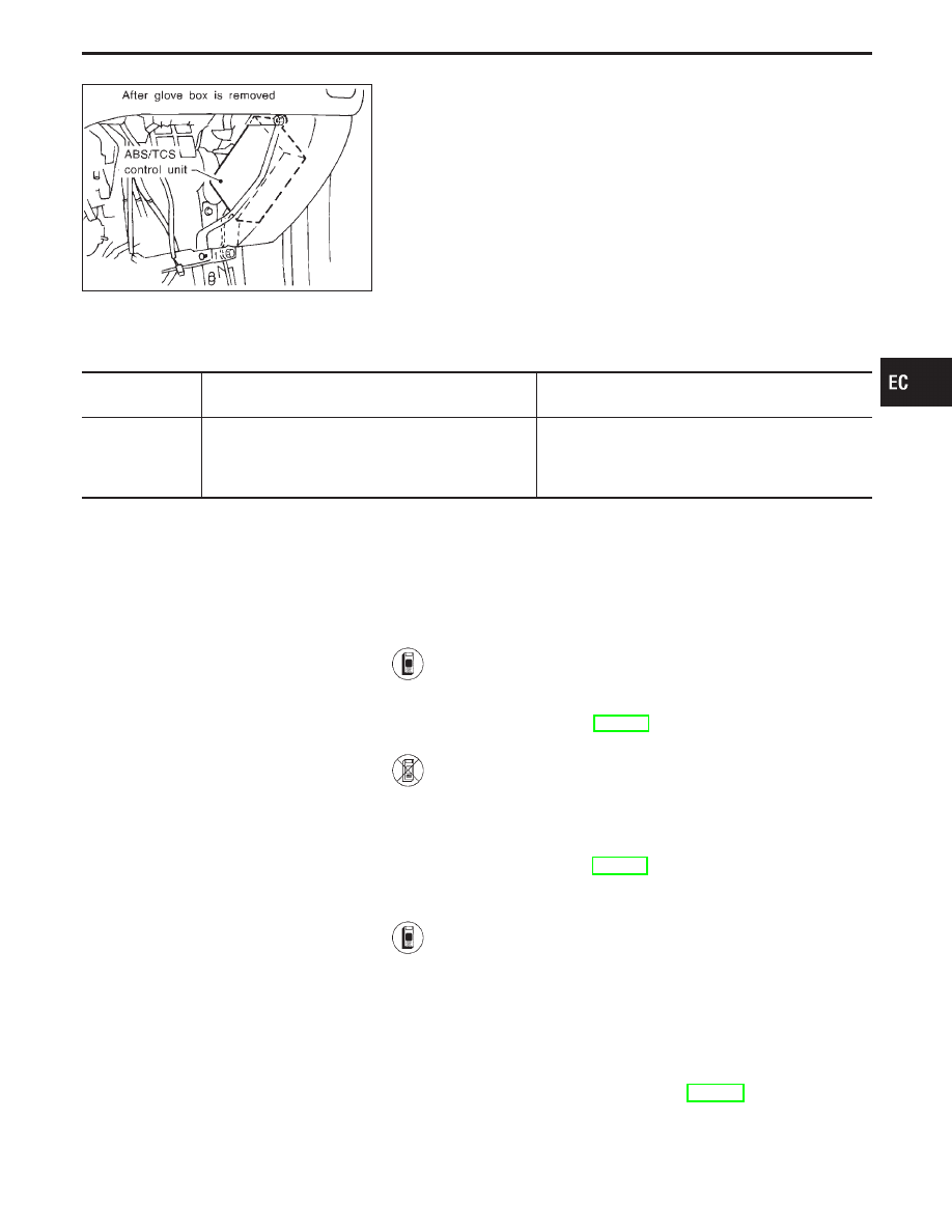
ABS/TCS Control Unit
The malfunction information related to ABS/TCS control unit is
transferred through the line (LAN) from ABS/TCS control unit to
ECM.
Be sure to erase the malfunction information such as DTC not
only for ABS/TCS control unit but also for ECM after the ABS/
TCS related repair.
Freeze frame data is not stored in the ECM for the ABS/TCS control unit. The MIL will not light up for
ABS/TCS control unit.
ON BOARD DIAGNOSIS LOGIC
Diagnostic Trouble
Code No.
Malfunction is detected when
Check Items
(Possible Cause)
—*
0107
I
ECM receives incorrect voltage from ABS/TCS con-
trol unit continuously.
I
Harness or connectors
(The circuit between ECM and ABS/TCS control unit
is open or shorted.)
I
ABS/TCS control unit
*: SAE J2012 number is not applicable
DIAGNOSTIC TROUBLE CODE CONFIRMATION
PROCEDURE
Before performing the following procedure, confirm that bat-
tery voltage is more than 10.5V.
1) Turn ignition switch “ON”.
2) Select “DATA MONITOR” mode with CONSULT-II.
3) Start engine and let it idle for at least 40 seconds.
4) If 1st trip DTC is detected, go to “DIAGNOSTIC
PROCEDURE”, EC-502.
------------------------------------------------------------------------------------------------------------------------------------------------------------------------------------------------------------------------------------------------------ OR ------------------------------------------------------------------------------------------------------------------------------------------------------------------------------------------------------------------------------------------------------
1) Start engine and let it idle for at least 40 seconds.
2) Turn ignition switch “OFF”, wait at least 5 seconds and
then turn “ON”.
3) Perform “Diagnostic Test Mode II (Self-diagnostic
results)” with ECM.
4) If 1st trip DTC is detected, go to “DIAGNOSTIC
PROCEDURE”, EC-502.
DTC erasing procedure for ABS/TCS related repair
Erase DTC code by following procedure:
1) Turn ignition switch “OFF” and then turn it “ON”.
2) Connect CONSULT-II and select “ABS”.
3) Insert UE990 card and install it.
4) Select “ABS” and touch “SELF-DIAG RESULTS”.
5) Touch “ERASE”.
6) Touch “BACK” then erase malfunction code which has
been stored in the TCM or ECM.
DIAGNOSTIC PROCEDURE
Refer to “DIAGNOSTIC PROCEDURE”, EC-502.
GI
MA
EM
LC
FE
AT
PD
FA
RA
BR
ST
RS
BT
HA
EL
IDX
TROUBLE DIAGNOSIS FOR ABS/TCS C/U SIGNAL
EC-499
ABS/TCS Communication Line
This circuit line is used to control the smooth engine operation of
ABS/TCS during the TCS operation. Pulse signals are exchanged
between ECM and ABS/TCS control unit.
Be sure to erase the malfunction information such as DTC not
only in ABS/TCS control unit but also ECM after the ABS/TCS
related repair. Refer to BR section (Self-diagnosis for ABS/
TCS control unit, “HOW TO ERASE SELF DIAGNOSTIC
RESULTS”).
Freeze frame data is not stored in the ECM for the ABS/TCS communication line. The MIL will not light
up for the ABS/TCS communication line.
ON BOARD DIAGNOSIS LOGIC
Diagnostic
Trouble
Code No.
Malfunction is detected when ...
Check Items
(Possible Cause)
—*
0404
I
ECM receives incorrect voltage from ABS/TCS control
unit continuously.
I
Harness or connectors
(The communication line circuit between ECM and
ABS/TCS control unit is open or shorted.)
I
ABS/TCS control unit
I
Dead (Weak) battery
*: SAE J2012 number is not applicable.
DIAGNOSTIC TROUBLE CODE CONFIRMATION
PROCEDURE
Before performing the following procedure, confirm that bat-
tery voltage is more than 10.5V.
1) Turn ignition switch “ON”.
2) Select “DATA MONITOR” mode with CONSULT-II.
3) Start engine and let it idle for at least 3 seconds.
4) If 1st trip DTC is detected, go to “DIAGNOSTIC
PROCEDURE”, EC-502.
------------------------------------------------------------------------------------------------------------------------------------------------------------------------------------------------------------------------------------------------------ OR ------------------------------------------------------------------------------------------------------------------------------------------------------------------------------------------------------------------------------------------------------
1) Start engine and let it idle for at least 3 seconds.
2) Turn ignition switch “OFF”, wait at least 5 seconds and
then turn “ON”.
3) Perform “Diagnostic Test Mode II (Self-diagnostic
results)” with ECM.
4) If 1st trip DTC is detected, go to “DIAGNOSTIC
PROCEDURE”, EC-502.
TROUBLE DIAGNOSIS FOR ECM — ABS/TCS COMM NG
EC-500
Нет комментариевНе стесняйтесь поделиться с нами вашим ценным мнением.
Текст