Infiniti Q45 (FY33). Manual — part 187
ON BOARD DIAGNOSIS LOGIC
Diagnostic
Trouble Code
No.
Malfunction is detected when .
Check Items
(Possible Cause)
P0340
0101
A) Either 1° or 90° signal is not sent to ECM for the first
few seconds during engine cranking.
. . . . . . . . . . . . . . . . . . . . . . ...
I
Harness or connectors
(The camshaft position sensor circuit is open or
shorted.)
I
Camshaft position sensor
I
Starter motor (Refer to EL section.)
I
Starting system circuit (Refer to EL section.)
I
Dead (Weak) battery
B) Either 1° or 90° signal is not sent to ECM during
engine running.
. . . . . . . . . . . . . . . . . . . . . . ...
C) Either 1° or 90° signal is not in the normal pattern
during engine running.
DIAGNOSTIC TROUBLE CODE CONFIRMATION
PROCEDURE
Perform “Procedure for malfunction A” first. If DTC cannot be
confirmed, perform “Procedure for malfunction B and C”.
NOTE:
If “DIAGNOSTIC TROUBLE CODE CONFIRMATION PROCE-
DURE” has been previously conducted, always turn ignition
switch “OFF” and wait at least 5 seconds before conducting
the next test.
TESTING CONDITION:
Before performing the following procedure, confirm that bat-
tery voltage is more than 10.5V at idle.
SEF400X
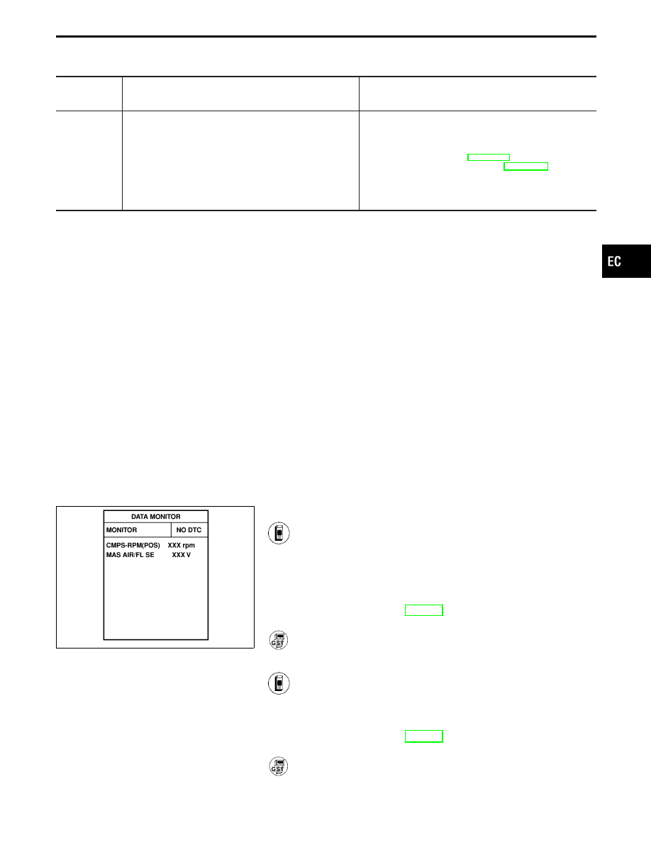
Procedure for malfunction A
1) Turn ignition switch “ON” and select “DATA MONITOR”
mode with CONSULT-II.
2) Start engine and run it for at least 2 seconds at idle
speed.
(If engine does not run, turn ignition switch to “START”
for at least 2 seconds.)
3) If 1st trip DTC is detected, go to “DIAGNOSTIC
PROCEDURE”, EC-279.
------------------------------------------------------------------------------------------------------------------------------------------------------------------------------------------------------------------------------------------------------ OR ------------------------------------------------------------------------------------------------------------------------------------------------------------------------------------------------------------------------------------------------------
Follow the procedure “With CONSULT-II” above.
Procedure for malfunction B and C
1) Turn ignition switch “ON”.
2) Select “DATA MONITOR” mode with CONSULT-II.
3) Start engine and run it for at least 2 seconds at idle
speed.
4) If 1st trip DTC is detected, go to “DIAGNOSTIC
PROCEDURE”, EC-279.
------------------------------------------------------------------------------------------------------------------------------------------------------------------------------------------------------------------------------------------------------ OR ------------------------------------------------------------------------------------------------------------------------------------------------------------------------------------------------------------------------------------------------------
Follow the procedure “With CONSULT-II” above.
GI
MA
EM
LC
FE
AT
PD
FA
RA
BR
ST
RS
BT
HA
EL
IDX
TROUBLE DIAGNOSIS FOR DTC P0340
Camshaft Position Sensor (CMPS) (Cont’d)
EC-277
TEC030M
TROUBLE DIAGNOSIS FOR DTC P0340
Camshaft Position Sensor (CMPS) (Cont’d)
EC-278
SEF802W
SEF377U
SEF872Q
SEF409U
SEF150T
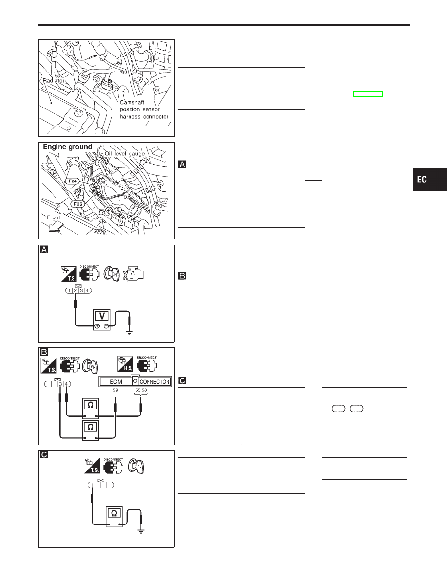
DIAGNOSTIC PROCEDURE
INSPECTION START
CHECK STARTING SYSTEM.
Does the engine turn over?
(Does the starter motor operate?)
Yes
E
No
Check starting system.
(Refer to EL section.)
1. Turn ignition switch “OFF”.
2. Loosen and retighten engine ground
screws.
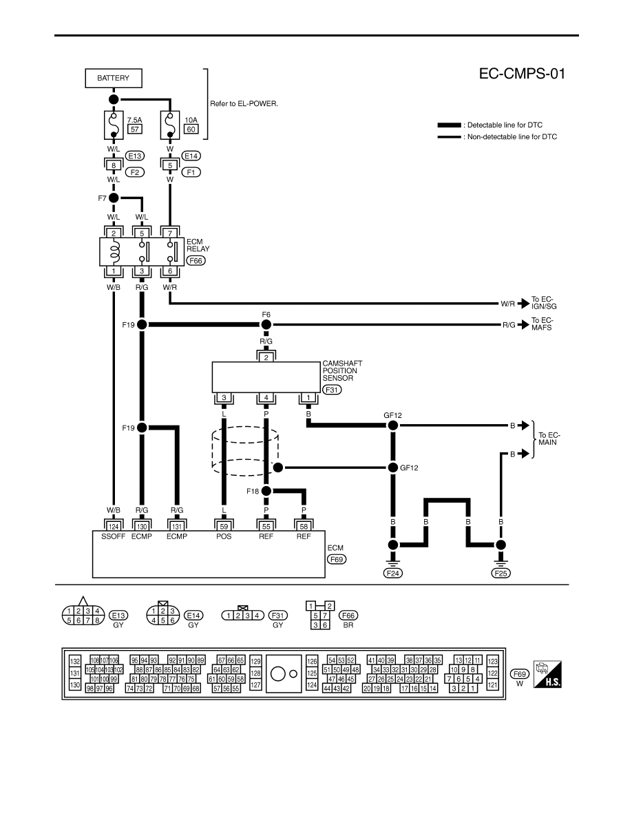
CHECK POWER SUPPLY.
1. Disconnect camshaft position sensor
harness connector.
2. Turn ignition switch “ON”.
3. Check voltage between terminal
q
2
and ground with CONSULT-II or tester.
Voltage: Battery voltage
OK
E
NG
Check the following.
I
Harness for open or
short between camshaft
position sensor and
ECM
I
Harness for open or
short between camshaft
position sensor and
ECM relay
If NG, repair open circuit or
short to ground and short
to power in harness or
connectors.
CHECK INPUT SIGNAL CIRCUIT.
1. Turn ignition switch “OFF”.
2. Disconnect camshaft position sensor
harness connector and ECM harness
connector.
3. Check harness continuity between ter-
minal
q
3
and ECM terminal
q
59
, terminal
q
4
and ECM terminals
q
55
,
q
58
.
Continuity should exist.
If OK, check harness for short to
ground and short to power.
OK
E
NG
Repair harness or connec-
tors.
CHECK GROUND CIRCUIT.
1. Turn ignition switch “OFF”.
2. Check harness continuity between ter-
minal
q
1
and engine ground.
Continuity should exist.
If OK, check harness for short to
power.
OK
E
NG
Check the following.
I
Harness connectors
F61
,
F62
If NG, repair open circuit or
short to power in harness
or connectors.
CHECK COMPONENT
[Camshaft position sensor].
Refer to “COMPONENT INSPECTION” on
next page.
OK
E
NG
Replace camshaft position
sensor.
q
A
(Go to next page.)
GI
MA
EM
LC
FE
AT
PD
FA
RA
BR
ST
RS
BT
HA
EL
IDX
TROUBLE DIAGNOSIS FOR DTC P0340
Camshaft Position Sensor (CMPS) (Cont’d)
H
H
H
H
H
H
H
EC-279
q
A
Perform “TROUBLE DIAGNOSIS FOR
INTERMITTENT INCIDENT”, EC-117.
Trouble is not fixed.
Visually check the surface of camshaft
sprocket for chipping.
OK
E
NG
Replace camshaft sprocket.
INSPECTION END
SEF839U
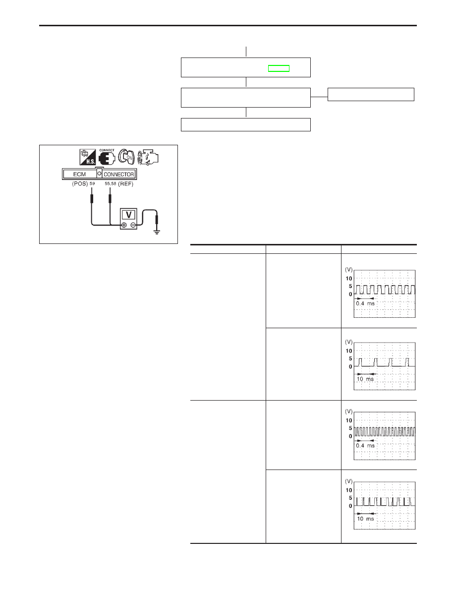
COMPONENT INSPECTION
Camshaft position sensor
1.
Start engine and warm it up to the normal operating tempera-
ture.
2.
Check voltage between ECM terminals
q
59
(POS) or
q
55
,
q
58
(REF) (ECM terminal) and ground with DC range.
CAUTION:
Do not use ECM ground terminals when measuring voltage.
Doing so may result in damage to the ECM’s transistor. Use a
ground other than ECM terminals such as the body ground.
Condition
Terminals
Voltage
Engine running at idle
q
59
and ground (POS)
Approx. 2.5V
SEF547T
q
55
,
q
58
and ground (REF)
Approx. 0.7 - 1.2V
SEF046V
Engine at 2,000 rpm
q
59
and ground (POS)
SEF548T
q
55
,
q
58
and ground (REF)
SEF544T
If NG, replace camshaft position sensor.
TROUBLE DIAGNOSIS FOR DTC P0340
Camshaft Position Sensor (CMPS) (Cont’d)
H
H
H
EC-280
Нет комментариевНе стесняйтесь поделиться с нами вашим ценным мнением.
Текст