Infiniti Q45 (FY33). Manual — part 252
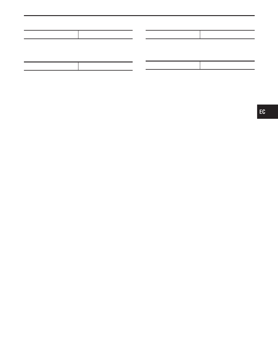
DROPPING RESISTOR
Resistance [at 25°C (77°F)]
Ω
Approximately 0.8
EVAP CANISTER PURGE VOLUME
CONTROL VALVE
Resistance [at 25°C (77°F)]
Ω
35 - 43
CRANKSHAFT POSITION SENSOR (OBD)
Resistance
Ω
166.5 - 203.5 [at 25°C (77°F)]
INTAKE VALVE TIMING CONTROL
POSITION SENSOR
Resistance [at 25°C (77°F)]
Ω
600 - 740
GI
MA
EM
LC
FE
AT
PD
FA
RA
BR
ST
RS
BT
HA
EL
IDX
SERVICE DATA AND SPECIFICATIONS (SDS)
Inspection and Adjustment (Cont’d)
EC-537
NOTES
ELECTRICAL SYSTEM
When you read wiring diagrams:
I
Read GI section, “HOW TO READ WIRING DIAGRAMS”.
When you perform trouble diagnoses, read GI section, “HOW TO FOLLOW FLOW CHART IN
TROUBLE DIAGNOSES” and “HOW TO PERFORM EFFICIENT DIAGNOSIS FOR AN ELECTRICAL
INCIDENT”.
I
Check for any service bulletins before servicing the vehicle.
CONTENTS
PRECAUTIONS . . . . . . . . . . . . . . . ...6
Supplemental Restraint System (SRS)
. . . ...6
PREPARATION . . . . . . . . . . . . . . . . 7
Special Service Tool . . . . . . . . . . . . . 7
HARNESS CONNECTOR. . . . . . . . . . . . 8
Description . . . . . . . . . . . . . . . . ...8
STANDARDIZED RELAY . . . . . . . . . . . ..10
Description . . . . . . . . . . . . . . . . .10
POWER SUPPLY ROUTING . . . . . . . . . . .12
Schematic . . . . . . . . . . . . . . . . ..12
Wiring Diagram - POWER - . . . . . . . . . ..13
Fuse . . . . . . . . . . . . . . . . . . ...22
Fusible Link. . . . . . . . . . . . . . . . 22
Circuit Breaker Inspection . . . . . . . . . . .22
GROUND DISTRIBUTION. . . . . . . . . . . .23
Engine Room Harness . . . . . . . . . . . ..23
Main Harness. . . . . . . . . . . . . . . .25
Engine Control Harness . . . . . . . . . . . 29
Engine Harness . . . . . . . . . . . . . . .31
Body Harness . . . . . . . . . . . . . . . 32
Body No. 2 Harness . . . . . . . . . . . . ..34
BATTERY . . . . . . . . . . . . . . . . . ...35
How to Handle Battery . . . . . . . . . . . ..35
Service Data and Specifications (SDS). . . . . .37
Trouble Diagnoses with Battery/Starting/Charging
System Tester . . . . . . . . . . . . . . . 38
STARTING SYSTEM . . . . . . . . . . . . . .41
System Description. . . . . . . . . . . . . 41
Wiring Diagram - START -. . . . . . . . . . .42
Trouble Diagnoses with Battery/Starting/Charging
System Tester . . . . . . . . . . . . . . . 43
Trouble Diagnoses. . . . . . . . . . . . . .45
Construction. . . . . . . . . . . . . . . ...47
Removal and Installation . . . . . . . . . . ...47
Pinion/Clutch Check . . . . . . . . . . . . ..48
Service Data and Specifications (SDS). . . . . .48
CHARGING SYSTEM . . . . . . . . . . . . . 49
System Description. . . . . . . . . . . . . 49
Wiring Diagram - CHARGE -. . . . . . . . . .50
Trouble Diagnoses with Battery/Starting/Charging
System Tester . . . . . . . . . . . . . . . 51
Removal and Installation . . . . . . . . . . ...56
Construction. . . . . . . . . . . . . . . ...57
Service Data and Specifications (SDS). . . . . .57
COMBINATION SWITCH. . . . . . . . . . . ...58
Check. . . . . . . . . . . . . . . . . . .58
Replacement. . . . . . . . . . . . . . . ..59
STEERING SWITCH. . . . . . . . . . . . . ..60
Check. . . . . . . . . . . . . . . . . . .60
HEADLAMP (FOR U.S.A.) - CONVENTIONAL
TYPE -. . . . . . . . . . . . . . . . . . . 62
Component Parts and Harness Connector
Location . . . . . . . . . . . . . . . . . .62
System Description. . . . . . . . . . . . . 62
Schematic . . . . . . . . . . . . . . . . ..64
Wiring Diagram - H/LAMP -. . . . . . . . . ...65
CONSULT-II (For auto light operation). . . . . ..68
Trouble Diagnoses/Auto Light Operation . . . . ..69
Trouble Diagnoses/Headlamp (Conventional
Type) . . . . . . . . . . . . . . . . . . ..75
Bulb Replacement/Conventional Type . . . . . ..76
Bulb Specifications/Conventional Type . . . . . .76
Aiming Adjustment/Conventional Type . . . . . ..76
HEADLAMP (FOR U.S.A.) - XENON TYPE -. . . ...78
Component Parts and Harness Connector
Location . . . . . . . . . . . . . . . . . .78
System Description. . . . . . . . . . . . . 78
Schematic . . . . . . . . . . . . . . . . ..81
Wiring Diagram - H/LAMP -. . . . . . . . . ...82
Trouble Diagnoses/Headlamp (Xenon Type) . . . 85
Bulb Replacement/Xenon Type . . . . . . . . .87
GI
MA
EM
LC
EC
FE
AT
PD
FA
RA
BR
ST
RS
BT
HA
IDX

Aiming Adjustment/Xenon Type. . . . . . . . .88
HEADLAMP (FOR CANADA) - CONVENTIONAL
TYPE -. . . . . . . . . . . . . . . . . . . 90
Component Parts and Harness Connector
Location . . . . . . . . . . . . . . . . . .90
Daytime Light System/System Description . . . ...90
Operation (Daytime light system with
conventional headlamp). . . . . . . . . . . .92
Schematic . . . . . . . . . . . . . . . . ..93
Wiring Diagram - DTRL -. . . . . . . . . . ...94
Trouble Diagnoses. . . . . . . . . . . . . .98
Bulb Replacement/Conventional Type . . . . . ..99
Bulb Specifications/Conventional Type . . . . . .99
Aiming Adjustment/Conventional Type . . . . . ..99
HEADLAMP (FOR CANADA) - XENON TYPE -. . 100
Component Parts and Harness Connector
Location . . . . . . . . . . . . . . . . ...100
Daytime Light System/System Description . . . .100
Operation (Daytime light system with xenon
headlamp) . . . . . . . . . . . . . . . . 102
Schematic . . . . . . . . . . . . . . . . 103
Wiring Diagram - DTRL -. . . . . . . . . . .104
Trouble Diagnoses. . . . . . . . . . . . ...108
Bulb Replacement/Xenon Type . . . . . . . ...109
Aiming Adjustment/Xenon Type. . . . . . . ...109
HEADLAMP - Headlamp Aiming Control -. . . ... 110
Wiring Diagram - H/AIM - . . . . . . . . . . 110
PARKING, LICENSE AND TAIL LAMPS . . . . . 111
System Description. . . . . . . . . . . . .. 111
Wiring Diagram - TAIL/L -. . . . . . . . . . 112
Trouble Diagnoses. . . . . . . . . . . . ... 114
STOP LAMP . . . . . . . . . . . . . . . . 115
Wiring Diagram - STOP/L - . . . . . . . . . . 115
BACK-UP LAMP. . . . . . . . . . . . . . .. 116
Wiring Diagram - BACK/L - . . . . . . . . . . 116
FRONT FOG LAMP. . . . . . . . . . . . . . 117
System Description. . . . . . . . . . . . .. 117
Wiring Diagram - F/FOG - . . . . . . . . . ... 118
Aiming Adjustment . . . . . . . . . . . . ...120
Bulb Specifications . . . . . . . . . . . . ..120
TURN SIGNAL AND HAZARD WARNING LAMPS ...121
System Description. . . . . . . . . . . . ..121
Schematic . . . . . . . . . . . . . . . . 123
Wiring Diagram - TURN - . . . . . . . . . . 124
Trouble Diagnoses. . . . . . . . . . . . ...127
Electrical Components Inspection . . . . . . ...127
ILLUMINATION . . . . . . . . . . . . . . . 128
System Description. . . . . . . . . . . . ..128
Schematic . . . . . . . . . . . . . . . . 129
Wiring Diagram - ILL - . . . . . . . . . . . .131
TRUNK ROOM AND VANITY MIRROR LAMP . . ..141
Wiring Diagram - INT/L - . . . . . . . . . . .141
METER AND GAUGES . . . . . . . . . . . ...142
Component Parts and Harness Connector
Location . . . . . . . . . . . . . . . . ...142
System Description. . . . . . . . . . . . ..142
Combination Meter . . . . . . . . . . . . ..144
Wiring Diagram - METER - . . . . . . . . . .145
Meter/Gauge Operation and Odo/Trip Meter
Segment Check in Diagnosis Mode . . . . . . 147
Flexible Print Circuit (FPC). . . . . . . . . ..148
Trouble Diagnoses. . . . . . . . . . . . ...149
Electrical Components Inspection . . . . . . ...153
WARNING LAMPS . . . . . . . . . . . . . ..156
System Description. . . . . . . . . . . . ..156
Schematic . . . . . . . . . . . . . . . . 159
Wiring Diagram - WARN - . . . . . . . . . ...160
CONSULT-II (For door warning lamp). . . . . .164
Trouble Diagnoses/Door Warning Lamp . . . . .165
Trouble Diagnoses/Stop and Tail Lamp Sensor. ..167
Electrical Components Inspection . . . . . . ...168
A/T INDICATOR . . . . . . . . . . . . . . ...169
Schematic . . . . . . . . . . . . . . . . 169
Wiring Diagram - AT/IND -. . . . . . . . . ...170
WARNING CHIME . . . . . . . . . . . . . ...173
Component Parts and Harness Connector
Location . . . . . . . . . . . . . . . . ...173
System Description. . . . . . . . . . . . ..173
Wiring Diagram - CHIME - . . . . . . . . . ..175
CONSULT-II . . . . . . . . . . . . . . . .177
Trouble Diagnoses. . . . . . . . . . . . ...178
Electrical Components Inspection . . . . . . ...182
WIPER AND WASHER . . . . . . . . . . . . 183
Component Parts and Harness Connector
Location . . . . . . . . . . . . . . . . ...183
System Description. . . . . . . . . . . . ..183
Schematic . . . . . . . . . . . . . . . . 185
Wiring Diagram - WIPER - . . . . . . . . . ..186
CONSULT-II . . . . . . . . . . . . . . . .189
Trouble Diagnoses. . . . . . . . . . . . ...192
Removal and Installation . . . . . . . . . . .198
Washer Nozzle Adjustment . . . . . . . . . .199
Washer Tube Layout . . . . . . . . . . . ...200
HORN . . . . . . . . . . . . . . . . . . ...201
Wiring Diagram - HORN - . . . . . . . . . ...201
CIGARETTE LIGHTER. . . . . . . . . . . . 202
Wiring Diagram - CIGAR -. . . . . . . . . ...202
CLOCK. . . . . . . . . . . . . . . . . . .203
Wiring Diagram - CLOCK -. . . . . . . . . ..203
REAR WINDOW DEFOGGER. . . . . . . . . .204
Component Parts and Harness Connector
Location . . . . . . . . . . . . . . . . ...204
System Description. . . . . . . . . . . . ..204
Wiring Diagram - DEF -. . . . . . . . . . ...206
CONTENTS
(Cont’d)
EL-2
Нет комментариевНе стесняйтесь поделиться с нами вашим ценным мнением.
Текст