Infiniti Q45 (FY33). Manual — part 61
SAT860A
DISASSEMBLY AND ASSEMBLY
Service procedures for forward and overrun clutches are essen-
tially the same as those for reverse clutch, with the following excep-
tion:
I
Check of forward clutch operation
SAT861A
I
Check of overrun clutch operation
SAT865A
I
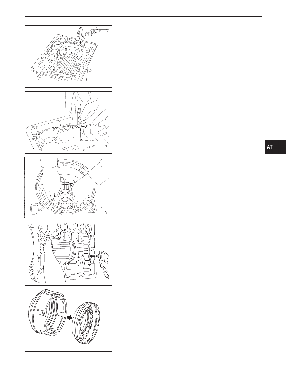
Removal of forward clutch drum
Remove forward clutch drum from transmission case by hold-
ing snap ring.
SAT862A
I
Removal of forward clutch and overrun clutch pistons
1.
While holding overrun clutch piston, gradually apply com-
pressed air to oil hole.
SAT863A
2.
Remove overrun clutch from forward clutch.
GI
MA
EM
LC
EC
FE
PD
FA
RA
BR
ST
RS
BT
HA
EL
IDX
REPAIR FOR COMPONENT PARTS
Forward and Overrun Clutches (Cont’d)
AT-241
SAT492G
I
Removal and installation of return springs
INSPECTION
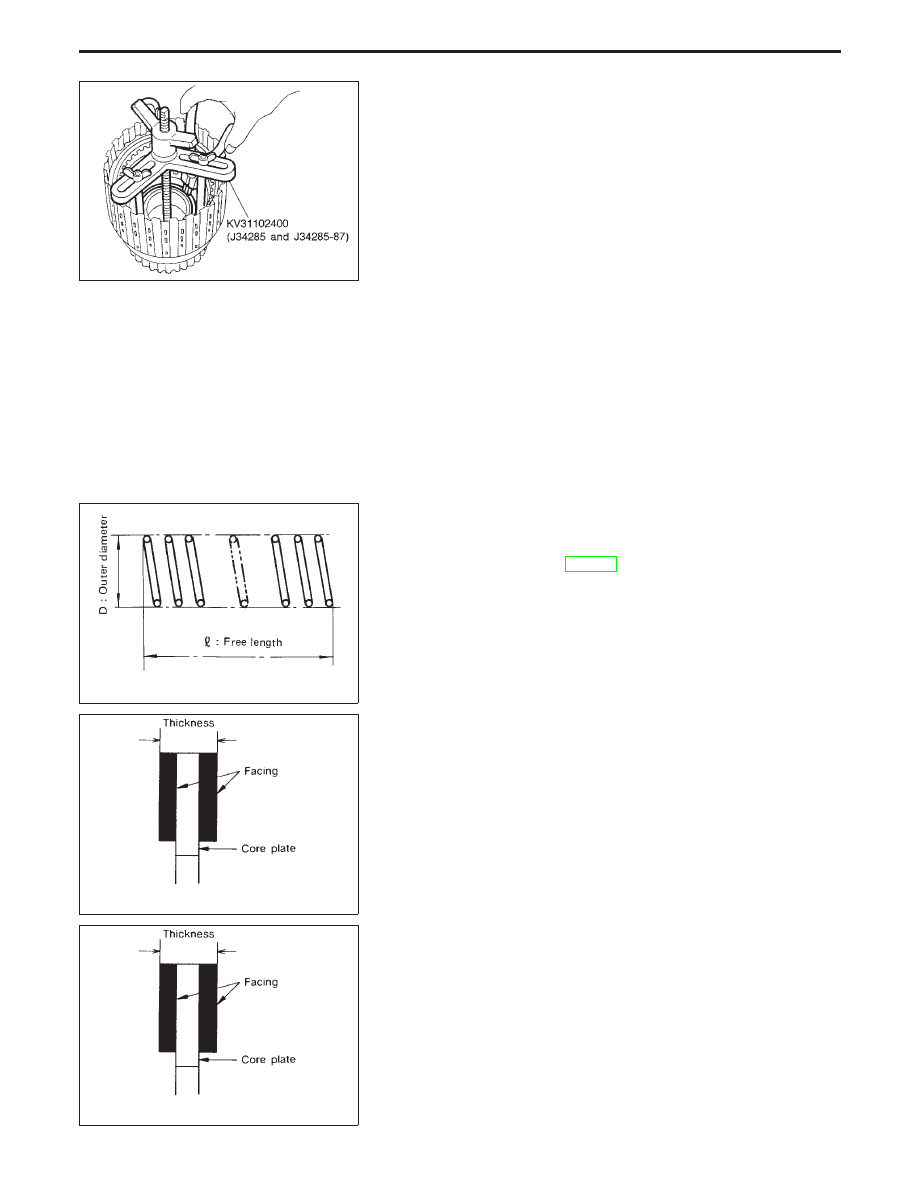
Forward and overrun clutch snap rings and spring
retainers
I
Check for deformation, fatigue or damage.
SAT829A
Forward and overrun clutch return springs
I
Inspection of forward clutch and overrun clutch return springs
Inspection standard:
Refer to SDS, AT-277.
SAT845A
I
Inspection of forward clutch drive plates
Thickness of drive plate:
Standard
1.90 - 2.05 mm (0.0748 - 0.0807 in)
Wear limit
1.6 mm (0.063 in)
SAT845A
I
Inspection of overrun clutch drive plates
Thickness of drive plate:
Standard
1.52 - 1.67 mm (0.0598 - 0.0657 in)
Wear limit
1.8 mm (0.071 in)
REPAIR FOR COMPONENT PARTS
Forward and Overrun Clutches (Cont’d)
AT-242
SAT741G
I
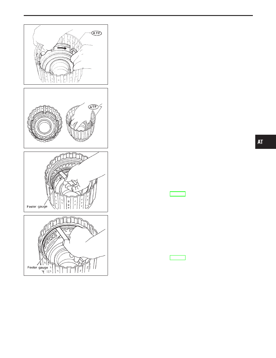
Installation of forward clutch piston and overrun clutch piston
1.
Install forward clutch piston by turning it slowly and evenly.
I
Apply ATF to inner surface of clutch drum.
SAT153G
I
Align notch in forward clutch piston with groove in for-
ward clutch drum.
2.
Install overrun clutch by turning it slowly and evenly.
I
Apply ATF to inner surface of forward clutch piston.
SAT869A
I
Measurement of clearance between retaining plate and snap
ring of overrun clutch
Specified clearance:
Standard
1.0 - 1.4 mm (0.039 - 0.055 in)
Allowable limit
2.2 mm (0.087 in)
Retaining plate:
Refer to SDS, AT-278.
SAT870A
I
Measurement of clearance between retaining plate and snap
ring of forward clutch
Specified clearance:
Standard
0.35 - 0.75 mm (0.0138 - 0.0295 in)
Allowable limit
1.95 mm (0.0768 in)
Retaining plate:
Refer to SDS, AT-278.
GI
MA
EM
LC
EC
FE
PD
FA
RA
BR
ST
RS
BT
HA
EL
IDX
REPAIR FOR COMPONENT PARTS
Forward and Overrun Clutches (Cont’d)
AT-243
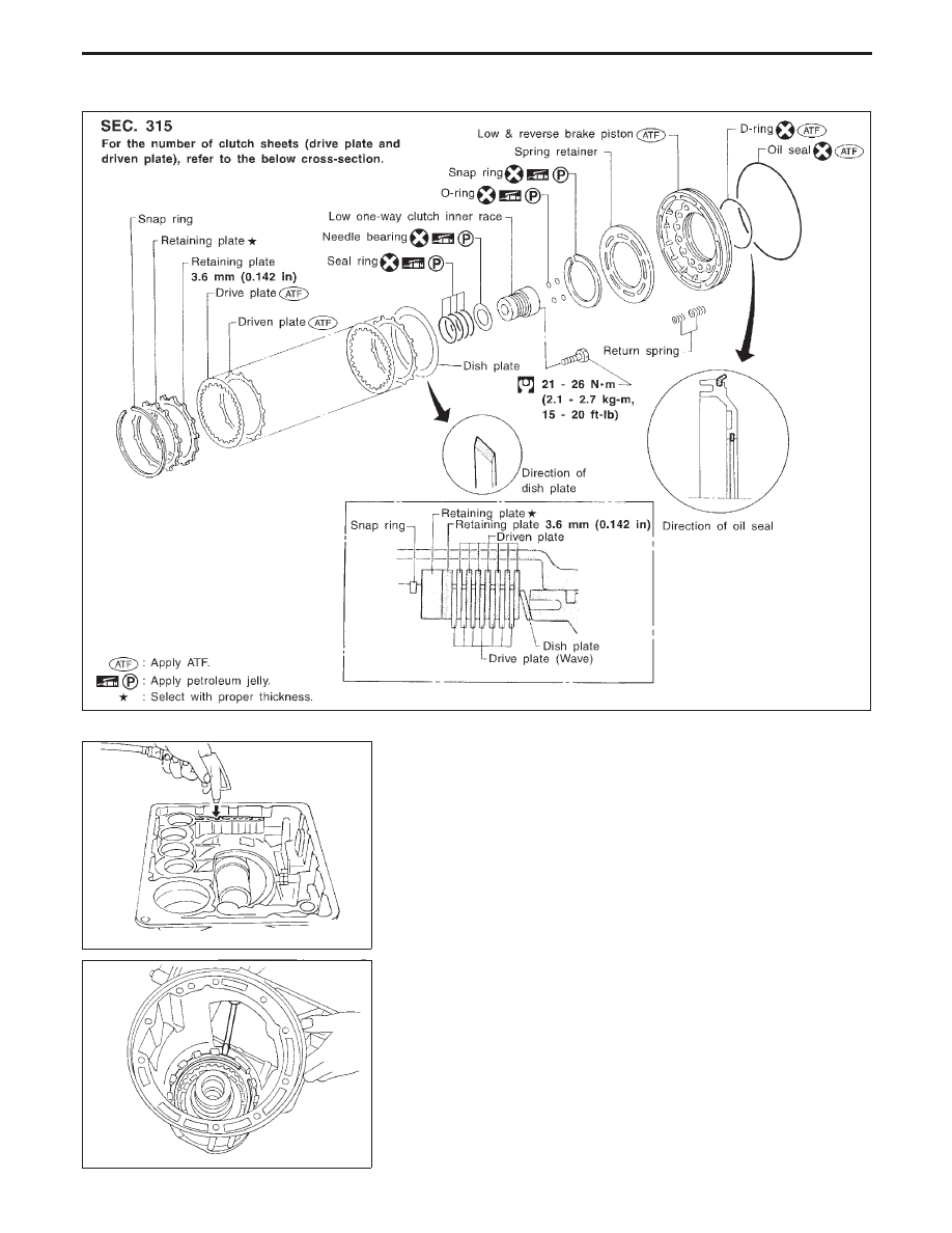
Low & Reverse Brake
SAT629I
SAT872A
DISASSEMBLY
1.
Check operation of low and reverse brake.
a.
Install seal ring onto oil pump cover and install reverse clutch.
Apply compressed air to oil hole.
b.
Check to see that retaining plate moves to snap ring.
c.
If retaining plate does not contact snap ring,
I
D-ring might be damaged.
I
Oil seal might be damaged.
I
Fluid might be leaking past piston check ball.
SAT873A
2.
Remove snap ring, low and reverse brake drive plates, driven
plates and dish plate.
REPAIR FOR COMPONENT PARTS
AT-244
Нет комментариевНе стесняйтесь поделиться с нами вашим ценным мнением.
Текст